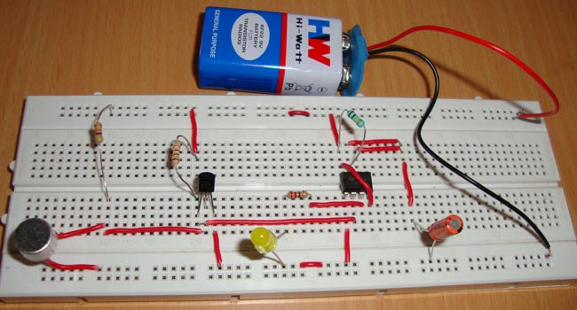
Clap switch is an interesting hobby circuit which turns on the lights with a clap sound. Although its name is “Clap switch”, but it can be turned ON by any sound of approximately same pitch of Clap sound. The main component of this clap switch circuit is the Electric Condenser Mic, which has been used as a sound sensor. Condenser Mic basically converts sound energy into electrical energy, that in turns used to trigger 555 timer IC, through a Transistor. And triggering of 555 IC would turn ON the LED, which will be automatically turned OFF after some time. I have made this circuit as simple as possible, you can find many complex Clap switches (using 555 IC) with some more components in it, and merely doing the same thing. Even make things simpler require more effort than making it complex.
Working Explanation
Here we are using Electric Condenser Mic for sensing the sound, transistor to trigger the 555 timer IC and 555 IC to turn ON the LED through a low voltage trigger.
Components
- Condenser Mic
- 555 Timer IC
- Transistor BC547
- Resistors (220, 1k, 47k, 100k ohm)
- Capacitor (10uF)
- LED
- Battery (5-9v) and Battery Snap Connector
- Breadboard Wires
- Breadboard
Circuit Diagram and Explanation
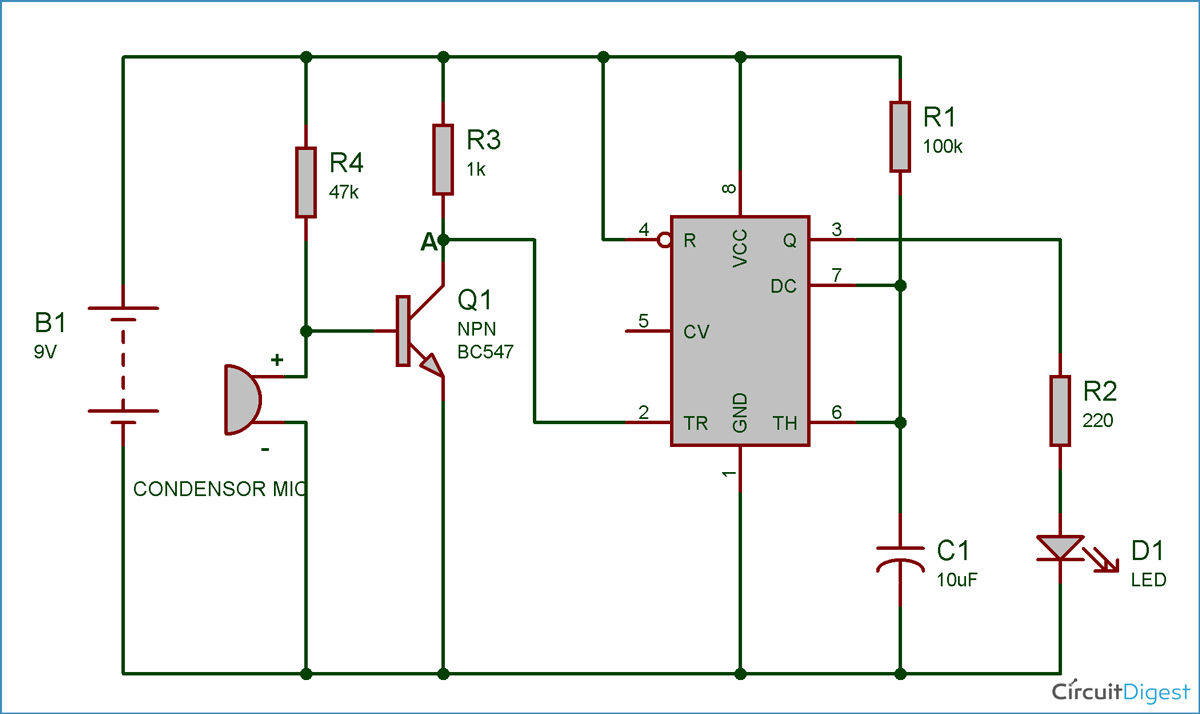
You can see the circuits and connections in the above schematic diagram of clap switch. Initially the transistor is in OFF state because there is not enough (0.7v) base-emitter voltage to turn it ON. And the point A is at high potential, and point A is connected to Trigger pin 2 of 555 IC, as a result Trigger pin 2 is also at high potential. As we know that, to trigger the 555 IC through Trigger PIN 2, the voltage of the PIN 2 must be below Vcc/3. So at this stage LED is OFF.
Now when we produce some sound near condenser mic, this sound will be converted into electrical energy and it will raise the potential at the Base, which will turn the Transistor ON. As soon as the transistor becomes ON, the potential at Point A would become low and it will trigger the 555 IC because of the low voltage (below Vcc/3) at Trigger Pin 2 and LED will turn ON. We have connected the LED to Output PIN 3 of 555 IC through a 220ohm resistor.
After some time LED will be turned OFF automatically because we are using 555 timer IC in Monostable Mode. LED will remain turned ON for 1.1*R1*C1 seconds. So we can see, with this formulae, that we can change this duration, by changing the value of Resistor R1 or/and Capacitor C1. We can modify this circuit using Relay to control the Electronic devices (120/220V AC). Control PIN 5 of 555 Timer IC should be connected to Ground through a 0.01uF capacitor.
To test this circuit you need to clap loudly as this small condenser mic don’t have long range. Or you can directly hit at the mic lightly (like I have done in the video).
In this circuit LED will be turned OFF automatically after some time, but what if we also want to control the switching OFF of the LED? Means if we want to turn ON the LED with a clap/sound and turn OFF it with second sound/clap? We can do this by using D-flipflop/IC 7474, I will show you this in my next circuit.
Comments
about the voltage of a 10uf capacitor i am also looking for a a
I want the same answer please tell if u solved it
1/8 W is fine except for LED
1/8 W is fine except for LED resistor. I would use 1/4W for that. WVDC for the cpa would be 12V or higher.
questions on clap switch
can u please help me in telling the questions that are commonly asked during the documentation of clap switch using 555 timer???
How about if i want to use
How about if i want to use more than one led?? Is there any changes to the values of the components??
Circuit will remain the same,
Circuit will remain the same, just connect second LED in parallel with existing LED with another 220ohm resistor. If you want to connect too many LEDs, then better connect them reversely, means negative legs connected to PIN 3 and Positive legs to Power supply.
Demo video itself showing
Demo video itself showing that it is working.
How are you simulating condenser mic in Multisim?
it is not working
it is not working because inthis ckt diagram first placed 47 k but in this video placed another resistor
i use a simple switch istead
i use a simple switch istead of mic in multisim....but now i was implemented on breadboard its doesnt work .....so plz tell me any solution
Double check the connections.
Double check the connections. And try using suitable Pull Up resistor for mic, try using 10k resistor.
yes, you can directly connect
yes, you can directly connect Relay Module to the output of the 555 timer.
problem in circuit
Hello! the circuit is not working properly when ever i connect the terminals of the battery the led is glowing constantly.I have checked the circuit many times but not getting any solution,need your help.
Please use the components of
Please use the components of given values.
explained
You know, it works, but NOT as you explained, in fact, it’s quite the opposite as you are explaining :
The microphone is working as a capacitor, so like an open switch for DC. This includes the transistor starts in ON state, and point A is at LOW potential (approx 0.2V), which means pin 2 of the 555 is also at LOW state and the Led is turning on (and by the working of the 555, it will be off after some time)
When a clap arrives at the mic, it will produce a sort of AC and the capacitor will act for a short period as a ‘closing’ switch. This means that the Transistor shall act as a barrier (the base will drop beneath the 0.7 V) and pin 2 get in HIGH state for a short time, and when the clap is done, it will get back to Low which will trigger the 555 again.
If you think I’m wrong, please use an oscilloscope to verify.
Can I connect a rectifier
Can I connect a rectifier circuit for supply ___?
yes, well-filtered, Amperage
yes, well-filtered, Amperage > 50 mA
would you do the same circuit
would you do the same circuit on PCB board?
Or at least send a link which shows it.
I made this circuit but this
I made this circuit but this didn't worked...I think that i need to connect a 100nf capacitor to pin 5 of ic 555 ...am i right please tell me......
Range of device
It is mentioned that : "small condenser mic don’t have long range", but can you tell the approximate range (in numeric value) of condenser mic where it can sense the sound. Thanks
need sm help
i created this circuit but when i connect battery to the circuit my LED turn on the moment i connect my battery but after 5-6 sec LED turns OFF and i try to clap to turn it on but its not working when i remove my battery and reconnect it to the circuit same thing happens
i waant to kno wht cud be the reason behind this ?
please help me
i m using 47uf capacitor i dont hv 10 uf
i want to know how to connect
i want to know how to connect a sound sensor with the 2 segment lcd display,so that it could count no of times a sound is made
Regarding clapping swith mic
Sir tell me which mic i will usr in make clapping swith. Tell me which mic i can use tell me about mic. Please sir
variable resistor for R4
You should consider using rheostat as R4 to adjust the sensitivity.
Led is continuasly on
I made the sketch twice with the components writen above, and the led is continuesly ON. Using 5v.
What should i do next?


what is the watt power of the resistor? 1 watt or 1/4 watt?, and also the capacitor, 10uF of what volts?, please be specific with your work, thanks