AC Waveform
As established in the first part of AC Circuit Theory, when a magnet rotates around a coil or a coil rotates around a magnetic field, an Alternating current or voltage is generated. The rotation of either the magnet or the coil which leads to the periodic alternation in direction and magnitude of the Voltage (or current) leads to the generation of some sort of wave when viewed on an oscilloscope or any other similar equipment. This waveform is as a result of the graphing of the voltage as it alternates over time. From the simple AC generator we described in the previous article, it can be seen that Alternating current or voltage is generically represented by the Sine wave (Sinusoid waveform) to the extent that in the development of inverters, they distinguish between inverters by describing certain inverters as pure sine wave inverters. The reason for this is that the sine wave represents a smooth transition, and rotation of the coil or magnet as the case may be.
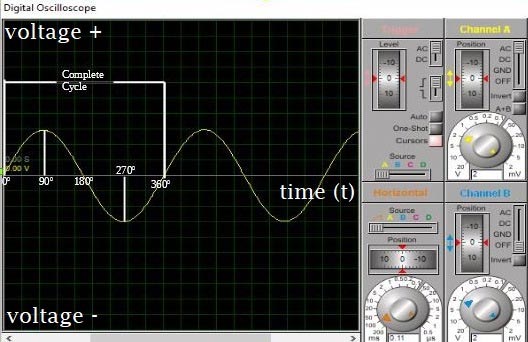
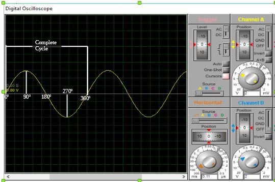
A Sinusoidal waveform representing the AC with all its features (which will be explained later in this article) is shown in the image below.
The science behind the waveform generation is better explained by Faraday’s Law of electromagnetic Induction which states that; the voltage produced by stationary coils as a result of the motion of a rotating magnet is proportional to the rate at which the magnetic flux is changing perpendicular to the coils.
The rate of the magnetic flux cutting the coil is greatest when the magnetic field is positioned in such a way that it cuts more conductor, and least when it is cutting less conductors, this determines the magnitude of the generated current or voltage, and as it continues to rotate, the direction changes.
Other Alternating Waveforms:
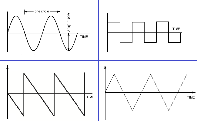
Before we dive into the properties of the AC waveform, its important to point out other useful waveform used in representing AC asides the sinusoidal waveform pattern, These wave forms include;
1. Square waves
2. Triangular Waves
3. Sawtooth or Ramp Wave forms
1. Square Waves
Square wave forms find major application in representing electrical signals like voltage, current and digital outputs and clock signals in digital electronics. When in either the negative or positive swing of the waveform, the duration for each the swings are always equal and they are thus said to be symmetrical. Square waves unlike sine waves, have vertical up and downs with flat top at the peak amplitude level instead of the progressively rising waveform with sharp peaks that characterizes the sine wave. They are basically referred to as square waves because of their flat tops. An example of a square wave is shown in the image below. Square wave forms can be easily generated with simple circuits.
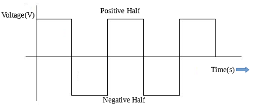
The frequency of a square wave is given by:
Frequency = 1 / period
Where, period = tp  + tn
tp = Time taken to complete positive half of a cycle
tn = Time taken to complete the negative half of the same cycle
2. Triangular Waves
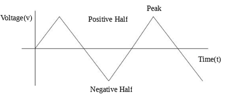
Triangular waves have a sharper peak edge compared to the sine wave. They have a slow rising and decay time. The triangular waves are equally periodic, and have equal rise and fall time. A sample of the triangular wave is shown in the image below.
3. Sawtooth waveform
The peak of the sawtooth wave form looks like that of a sawtooth, hence the name. Sawtooth waveform are basically of two types; the positive ramp characterized by high steep decay and slow rising time, and the negative ramp wave form characterized by slow steep decay and fast rising time. Images to differentiate between the two wave forms are shown below.
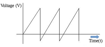
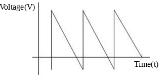
These three wave forms mentioned above are not the only one that can be used in describing AC wave forms, but they are the most popular and common kind of waveform that possesses a name and is deserving of a mention. All wave forms used to represent AC have something in common and that’s the periodic change in direction and magnitude this makes the “period” a very important property of AC waveform.
Properties of AC Waveform:
To completely and correctly describe an AC waveform, three properties are involved;
1. Amplitude
2. Frequency (or Period)
3. Phase
1. Amplitude
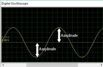
The Amplitude of an AC waveform is the magnitude of the AC waveform at any particular instant. The magnitude of the Alternating current or voltage varies with the sine of the angle made by the circular movement of the magnet or coil with respect to the zero point. For instance, when the coil made an angle of 90 degrees with the magnetic field as shown in the image below, the amplitude becomes 1 as the sine of 90 is 1, as this is the highest point, it is referred to as the peak voltage (or current) which will be better explained later. When the angle becomes 270 degrees, amplitude becomes -1 which is the magnitude of the maximum reverse voltage (or Current).
2. Frequency and Period
The coil or magnet rotates continuously means after the first complete rotation that the waveform repeats itself, this means we could thus select a point irrespective of its location on the waveform and use it as a sort of marker. Every time the wave reaches this particular point after repeating itself, the wave is said to have gone through a complete cycle and the number of complete cycle increases as the waveform keeps repeating itself. This is most easily explained by selecting the peak of the waveform as our marker, the distance between two successive peaks then describes a complete a cycle.
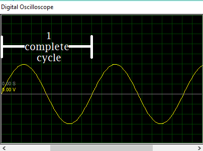
The cycle is measured in degrees, and when cycle is measured in time, it is described as a “period”. One complete cycle of an Alternating current or voltage is always 360 degrees, but the rate (i.e time) of alternation (or rotation) to achieve the period is described by the property referred to as “Frequency”.
Frequency of the AC waveform can thus be defined as the number of complete cycles (or periods) completed by the waveform per unit of time. The Unit of frequency is hertz (Hz), which simply represents the amount of cycles (or period) completed by the waveform in one seconds. Frequency is calculated using the formula;
Frequency =  1 / period
and
Period = 1 / frequency
The Frequency of AC supply in most part of the world is usually either 50Hz (Nigeria and Most European Countries) or 60 Hz in EU countries, and most plugged-in devices are always designed to handle this difference in frequency so devices can be used in any of these countries.
3. Phase
The Horizontal part of the sinusoidal waveform used in representing the Alternating current represents time, and based on time, the events to the right side of the graph are the later events, while the events to the left side of the graph are the former events. Since we are representing the Horizontal axis as time, when two waves of the same frequency start their cycles at different times, a phase difference measured in degrees is said to exist between them. This creates room for calculation without the use of frequency and also makes it easy to compare two waveforms with the same frequency. Consider the Images below;
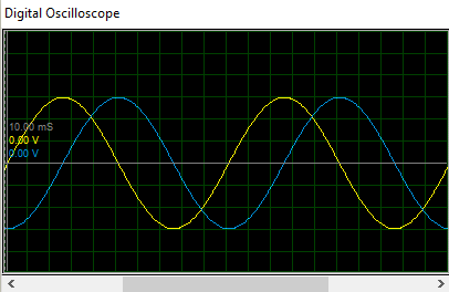
Above figure can be used to explain all the concepts of phase. In the figure above, Waveform “B” starts its cycle 900 late compared to waveform “Y”, thus waveform “B” is said to lag waveform “Y” by 900 and waveform “Y” can be said to be leading waveform “B” by 900.
We will stop here today, and in the next part of this post, we will focus on the mathematics of Alternating currents. Don’t forget to leave your questions and comments under the comments section.
Till next time,
Cheers!


Newt like a refresher on things!!