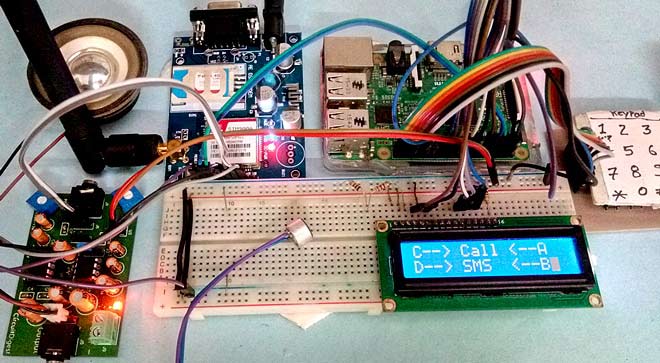
In this DIY project we are going to build a Simple Mobile Phone using Raspberry Pi, in which GSM Module is used to Make or answer the Call and send or read the SMS, and also this Raspberry Pi phone has Mic and Speaker to talk over this Phone. This project will also serve as a proper interfacing of GSM Module with Raspberry Pi, with all the Code needed to operate any Phone’s basic functions. Previously we have built same kind of Simple Mobile Phone using Arduino, check here
Required Components:
- Raspberry Pi 3 (any model)
- GSM Module
- 16x2 LCD
- 4x4 Keypad (user may use membrane keypad)
- 10k pot
- Breadboard
- Connecting jumper wire
- Power supply
- Speaker
- MIC
- SIM Card
- Speaker
- Audio Amplifier Circuit (Optional)
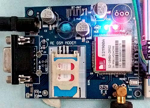
Working Explanation:
In this Raspberry Pi Mobile Phone Project, we have used GSM module and Raspberry Pi 3 to control whole system’s features and interfacing all the components in this system. A 4x4 Alphanumeric Keypad is used for taking all kind of inputs like: Enter mobile number, type messages, make a call, receive a call, send SMS, read SMS etc. GSM Module SIM900A is used to communicate with the network for calling and messaging purpose. We have also interfaced a MIC and a Speaker for Voice Call and Ring sound and a 16x2 LCD is used for showing messages, instructions and alerts.
Alphanumeric is a method to enter numbers and alphabets both by using same keypad. In this method, we have interfaced 4x4 keypad with Raspberry Pi and written Code for accepting alphabets too, check the Code in Code section below.
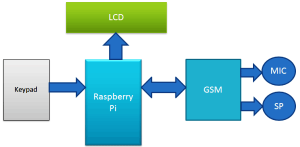
Working of this project is easy. All the features will be performed by Using Alphanumeric Keypad. Check the Full code and a Demo Video below to properly understand the process. Here we are going to explain all the four features of the projects below.
Explaining Four Features of Raspberry Pi Mobile Phone:
1. Make a Call:
To make a call by using our Raspberry Pi based Phone, we have to press ‘C’ and then need to enter the Mobile Number on which we want to make a call. Number will be entered by using alphanumeric keypad. After entering the number we again need to press ‘C’. Now Raspberry Pi will process for connecting the call to the entered number by using AT command:
ATDxxxxxxxxxx; <Enter> where xxxxxxxxx is entered Mobile Number.
2. Receive a Call:
Receiving a call is very easy. When someone is calling to your system SIM number, which is there in GSM Module, then your system will show ‘Incoming…’ message over the LCD with incoming number of caller. Now we just need to Press ‘A’ to attend this call. When we press ‘A’, Raspberry Pi will send given command to GSM Module:
ATA <enter>
3. Send SMS:
When we want to send a SMS using our Raspberry Pi based Phone, then we need to Press ‘D’. Now System will ask for Recipient Number, means ‘to whom’ we want to send SMS. After entering the number we need to again press ‘D’ and now LCD asks for message. Now we need to type the message, like we enter in normal mobile, by using keypad and then after entering the message we need to press the ‘D’ again to send SMS. To Send SMS Raspberry Pi sends given command:
AT+CMGF=1 <enter>
AT+CMGS=”xxxxxxxxxx” <enter>     where: xxxxxxxxxx is entered mobile number
And send 26 to GSM to send SMS.
4. Receive and Read SMS:
This feature is also simple. In this, GSM will receive SMS and stores it in SIM card. And Raspberry Pi continuously monitors the received SMS indication over UART. Whenever there is a new message LCD will show “New message” text and then we just need to Press ‘B’, to read the SMS. SMS Received indication is:
+CMTI: “SM”,6 Where 6 is message location where it stored in SIM card.
When Raspberry Pi gets this ‘SMS received’ indication then it extracts SMS storing location and sends command to GSM to read the received SMS. And show a ‘New Message’ text over the LCD.
AT+CMGR=<SMS stored location><enter>
Now GSM sends stored message to Raspberry Pi and then Raspberry Pi extract main SMS and display it over the LCD.
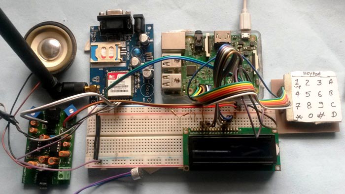
Note: There is no coding for MIC and Speaker.
Check the Full code and a Demo Video below to properly understand the process.
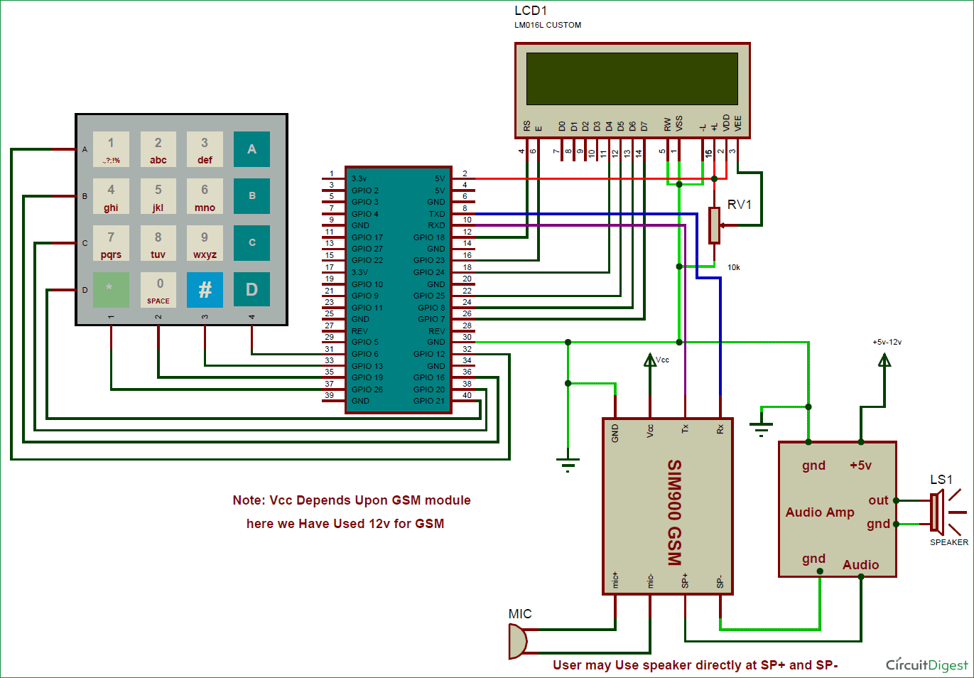
Circuit Diagram and Explanation:
16x2 LCD pins RS, EN, D4, D5, D6, and D7 are connected with GPIO pin number 18, 23, 24, 25, 8 and 7 of Raspberry Pi respectively. GSM Module’s Rx and Tx pin is directly connected to Raspberry Pi’s pin Tx and Rx respectively (Ground of Raspberry Pi and GSM must be connected with each other). 4x4 keypad Row pins R1, R2, R3, R4 are directly linked to GPIO pin number 12,16, 20, 21 of Raspberry Pi and Column pin of keypad C1, C2, C3, C4 are linked with GPIO pin number 26, 19, 13 and 6 of Raspberry Pi. MIC is directly connected to mic+ and mic- of GSM Module and the speaker is connected at sp+ and sp- pins for GSM Module with the help of this Audio Amplifier Circuit, to amplify the output audio. This Audio Amplifier circuit is optional and you can directly connect the speaker to GSM module without this Audio Amplifier.
Programming Explanation:
Programming part of this Raspberry Pi Mobile Phone is a little complex for beginners. We are using Python language here for the Program. If you are a beginner in Raspberry Pi, you should check our previous tutorials for Getting Started with Raspberry Pi and Installing & Configuring Raspbian Jessie OS in Pi.
In this code, we have created def keypad(): function for interfacing simple keypad for entering numbers. And for entering alphabets, we have created def alphaKeypad(): so that same keypad can be used to enter the alphabets as well. Now we have made this keypad multi functioning same as Arduino keypad library. By using this keypad we can enter characters and integer by using only 10 keys.
Like if we press key 2 (abc2), it will show ‘a’ and if we presses it again then it will replace ‘a’ to ‘b’ and if again we press three times then it will show ‘c’ at same place in LCD. If we wait for some time after pressing key, cursor will automatic move to next position in LCD. Now we can enter next char or number. The same procedure is applied for other keys.
def keypad():
   for j in range(4):
     gpio.setup(COL[j], gpio.OUT)
     gpio.output(COL[j], 0)
     ch=0
     for i in range(4):
       if gpio.input(ROW[i])==0:
         ch=MATRIX[i][j]
         return ch
         while (gpio.input(ROW[i]) == 0):
           pass
     gpio.output(COL[j],1)
def alphaKeypad():
    lcdclear()
    setCursor(x,y)
    lcdcmd(0x0f)
    msg=""
    while 1:
        key=0
        count=0
        key=keypad()
        if key == '1':
            ind=0
            maxInd=6
            Key='1'
            getChar(Key, ind, maxInd)
            .... .....
            ..... .....
First of all, in this python script we have included some required libraries and defined pins for LCD, keypad and other components:
import RPi.GPIO as gpio
import serial
import time

msg=""
alpha="1!@.,:?ABC2DEF3GHI4JKL5MNO6PQRS7TUV8WXYZ90 *#"
x=0
y=0

MATRIX = [
            ['1','2','3','A'],
            ['4','5','6','B'],
            ['7','8','9','C'],
            ['*','0','#','D']
         ]
ROW = [21,20,16,12]
COL = [26,19,13,6]
... .....
..... .....
Now it’s time to give direction to the pins:
gpio.setwarnings(False)
gpio.setmode(gpio.BCM)
gpio.setup(RS, gpio.OUT)
gpio.setup(EN, gpio.OUT)
gpio.setup(D4, gpio.OUT)
gpio.setup(D5, gpio.OUT)
gpio.setup(D6, gpio.OUT)
gpio.setup(D7, gpio.OUT)
gpio.setup(led, gpio.OUT)
gpio.setup(buz, gpio.OUT)
gpio.setup(m11, gpio.OUT)
gpio.setup(m12, gpio.OUT)
gpio.setup(button, gpio.IN)
gpio.output(led , 0)
gpio.output(buz , 0)
gpio.output(m11 , 0)
gpio.output(m12 , 0)
Then initialize Serial communication like below:
Serial = serial.Serial("/dev/ttyS0", baudrate=9600, timeout=2)
Now we need to write some function for driving LCD. Function def lcdcmd(ch): is used for sending command to LCD and def lcdwrite(ch): function is used for sending data to LCD. Along with these functions, def lcdclear(): is used to clear the LCD, def setCursor(x,y): is used to set cursor position at the LCD and def lcdprint(Str): is used to print string on LCD.
def lcdcmd(ch):
  gpio.output(RS, 0)
  gpio.output(D4, 0)
  gpio.output(D5, 0)
  gpio.output(D6, 0)
  gpio.output(D7, 0)
  if ch&0x10==0x10:
    gpio.output(D4, 1)
    .... .....
    ..... ....
def lcdwrite(ch):
  gpio.output(RS, 1)
  gpio.output(D4, 0)
  gpio.output(D5, 0)
  gpio.output(D6, 0)
  gpio.output(D7, 0)
  if ch&0x10==0x10:
    gpio.output(D4, 1)
  if ch&0x20==0x20:
    gpio.output(D5, 1)
    .... .....
    ..... ....
def lcdclear():
  lcdcmd(0x01)

def lcdprint(Str):
  l=0;
  l=len(Str)
  for i in range(l):
    lcdwrite(ord(Str[i]))
def setCursor(x,y):
    if y == 0:
        n=128+x
    elif y == 1:
        n=192+x
    lcdcmd(n)
After this we need to write some functions for sending SMS, receiving SMS, making a call and attending the call.
Function def call(): is used for making the call. And function def receiveCall(data): is used to showing the incoming message and number on LCD. Finally def attendCall(): is used to attend the call.
Function def sendSMS(): is used to write and send the message with the help of alphaKeypad() function. And function def receiveSMS(data): is used receive and retrieve the location of SMS. Finally def readSMS(index): is used to display the message on LCD.
You can find all the above functions in Code given below.
So this is how you can convert your Raspberry Pi into a mobile phone with help of GSM module. Also check this Raspberry Pi Touch Screen Smart Phone.
import RPi.GPIO as gpio
import serial
import time
msg=""
# 0 7 11 15 19 23 27 32 36 414244 ROLL45
alpha="1!@.,:?ABC2DEF3GHI4JKL5MNO6PQRS7TUV8WXYZ90 *#"
x=0
y=0
MATRIX = [
['1','2','3','A'],
['4','5','6','B'],
['7','8','9','C'],
['*','0','#','D']
]
ROW = [21,20,16,12]
COL = [26,19,13,6]
moNum=['0','0','0','0','0','0','0','0','0','0']
m11=17
m12=27
led=5
buz=26
button=19
RS =18
EN =23
D4 =24
D5 =25
D6 =8
D7 =7
HIGH=1
LOW=0
gpio.setwarnings(False)
gpio.setmode(gpio.BCM)
gpio.setup(RS, gpio.OUT)
gpio.setup(EN, gpio.OUT)
gpio.setup(D4, gpio.OUT)
gpio.setup(D5, gpio.OUT)
gpio.setup(D6, gpio.OUT)
gpio.setup(D7, gpio.OUT)
gpio.setup(led, gpio.OUT)
gpio.setup(buz, gpio.OUT)
gpio.setup(m11, gpio.OUT)
gpio.setup(m12, gpio.OUT)
gpio.setup(button, gpio.IN)
gpio.output(led , 0)
gpio.output(buz , 0)
gpio.output(m11 , 0)
gpio.output(m12 , 0)
for j in range(4):
gpio.setup(COL[j], gpio.OUT)
gpio.setup(COL[j],1)
for i in range (4):
gpio.setup(ROW[i],gpio.IN,pull_up_down=gpio.PUD_UP)
Serial = serial.Serial("/dev/ttyS0", baudrate=9600, timeout=2)
data=""
def begin():
lcdcmd(0x33)
lcdcmd(0x32)
lcdcmd(0x06)
lcdcmd(0x0C)
lcdcmd(0x28)
lcdcmd(0x01)
time.sleep(0.0005)
def lcdcmd(ch):
gpio.output(RS, 0)
gpio.output(D4, 0)
gpio.output(D5, 0)
gpio.output(D6, 0)
gpio.output(D7, 0)
if ch&0x10==0x10:
gpio.output(D4, 1)
if ch&0x20==0x20:
gpio.output(D5, 1)
if ch&0x40==0x40:
gpio.output(D6, 1)
if ch&0x80==0x80:
gpio.output(D7, 1)
gpio.output(EN, 1)
time.sleep(0.005)
gpio.output(EN, 0)
# Low bits
gpio.output(D4, 0)
gpio.output(D5, 0)
gpio.output(D6, 0)
gpio.output(D7, 0)
if ch&0x01==0x01:
gpio.output(D4, 1)
if ch&0x02==0x02:
gpio.output(D5, 1)
if ch&0x04==0x04:
gpio.output(D6, 1)
if ch&0x08==0x08:
gpio.output(D7, 1)
gpio.output(EN, 1)
time.sleep(0.005)
gpio.output(EN, 0)
def lcdwrite(ch):
gpio.output(RS, 1)
gpio.output(D4, 0)
gpio.output(D5, 0)
gpio.output(D6, 0)
gpio.output(D7, 0)
if ch&0x10==0x10:
gpio.output(D4, 1)
if ch&0x20==0x20:
gpio.output(D5, 1)
if ch&0x40==0x40:
gpio.output(D6, 1)
if ch&0x80==0x80:
gpio.output(D7, 1)
gpio.output(EN, 1)
time.sleep(0.005)
gpio.output(EN, 0)
# Low bits
gpio.output(D4, 0)
gpio.output(D5, 0)
gpio.output(D6, 0)
gpio.output(D7, 0)
if ch&0x01==0x01:
gpio.output(D4, 1)
if ch&0x02==0x02:
gpio.output(D5, 1)
if ch&0x04==0x04:
gpio.output(D6, 1)
if ch&0x08==0x08:
gpio.output(D7, 1)
gpio.output(EN, 1)
time.sleep(0.005)
gpio.output(EN, 0)
def lcdclear():
lcdcmd(0x01)
def lcdprint(Str):
l=0;
l=len(Str)
for i in range(l):
lcdwrite(ord(Str[i]))
def setCursor(x,y):
if y == 0:
n=128+x
elif y == 1:
n=192+x
lcdcmd(n)
def keypad():
for j in range(4):
gpio.setup(COL[j], gpio.OUT)
gpio.output(COL[j], 0)
ch=0
for i in range(4):
if gpio.input(ROW[i])==0:
ch=MATRIX[i][j]
#lcdwrite(ord(ch))
# print "Key Pressed:",ch
# time.sleep(2)
return ch
while (gpio.input(ROW[i]) == 0):
pass
gpio.output(COL[j],1)
# callNum[n]=ch
def serialEvent():
data = Serial.read(20)
#if data != '\0':
print data
data=""
def gsmInit():
lcdclear()
lcdprint("Finding Module");
time.sleep(1)
while 1:
data=""
Serial.write("AT\r");
data=Serial.read(10)
print data
r=data.find("OK")
if r>=0:
break
time.sleep(0.5)
while 1:
data=""
Serial.write("AT+CLIP=1\r");
data=Serial.read(10)
print data
r=data.find("OK")
if r>=0:
break
time.sleep(0.5)
lcdclear()
lcdprint("Finding Network")
time.sleep(1)
while 1:
data=""
Serial.flush()
Serial.write("AT+CPIN?\r");
data=Serial.read(30)
print data
r=data.find("READY")
if r>=0:
break
time.sleep(0.5)
lcdclear()
lcdprint("Finding Operator")
time.sleep(1)
while 1:
data=""
Serial.flush()
Serial.read(20)
Serial.write("AT+COPS?\r");
data=Serial.read(40)
#print data
r=data.find("+COPS:")
if r>=0:
l1=data.find(",\"")+2
l2=data.find("\"\r")
operator=data[l1:l2]
lcdclear()
lcdprint(operator)
time.sleep(3)
print operator
break;
time.sleep(0.5)
Serial.write("AT+CMGF=1\r");
time.sleep(0.5)
# Serial.write("AT+CNMI=2,2,0,0,0\r");
# time.sleep(0.5)
Serial.write("AT+CSMP=17,167,0,0\r");
time.sleep(0.5)
def receiveCall(data):
inNumber=""
r=data.find("+CLIP:")
if r>0:
inNumber=""
inNumber=data[r+8:r+21]
lcdclear()
lcdprint("incoming")
setCursor(0,1)
lcdprint(inNumber)
time.sleep(1)
return 1
def receiveSMS(data):
print data
r=data.find("\",")
print r
if r>0:
if data[r+4] == "\r":
smsNum=data[r+2:r+4]
elif data[r+3] == "\r":
smsNum=data[r+2]
elif data[r+5] == "\r":
smsNum=data[r+2:r+5]
else:
print "else"
print smsNum
if r>0:
lcdclear()
lcdprint("SMS Received")
setCursor(0,1)
lcdprint("Press Button B")
print "AT+CMGR="+smsNum+"\r"
time.sleep(2)
return str(smsNum)
else:
return 0
def attendCall():
print "Attend call"
Serial.write("ATA\r")
data=""
data=Serial.read(10)
l=data.find("OK")
if l>=0:
lcdclear()
lcdprint("Call attended")
time.sleep(2)
flag=-1;
while flag<0:
data=Serial.read(12);
print data
flag=data.find("NO CARRIER")
#flag=data.find("BUSY")
print flag
lcdclear()
lcdprint("Call Ended")
time.sleep(1)
lcdclear()
def readSMS(index):
print index
Serial.write("AT+CMGR="+index+"\r")
data=""
data=Serial.read(200)
print data
r=data.find("OK")
if r>=0:
r1=data.find("\"\r\n")
msg=""
msg=data[r1+3:r-4]
lcdclear()
lcdprint(msg)
print msg
time.sleep(5)
lcdclear();
smsFlag=0
print "Receive SMS"
def getChar(Key, ind, maxInd):
ch=0
ch=ind
lcdcmd(0x0e)
Char=''
count=0
global msg
global x
global y
while count<20:
key=keypad()
print key
if key== Key:
setCursor(x,y)
Char=alpha[ch]
lcdwrite(ord(Char))
ch=ch+1
if ch>maxInd:
ch=ind
count=0
count=count+1
time.sleep(0.1)
msg+=Char
x=x+1
if x>15:
x=0
y=1
lcdcmd(0x0f)
def alphaKeypad():
lcdclear()
setCursor(x,y)
lcdcmd(0x0f)
msg=""
while 1:
key=0
count=0
key=keypad()
if key == '1':
ind=0
maxInd=6
Key='1'
getChar(Key, ind, maxInd)
elif key == '2':
ind=7
maxInd=10
Key='2'
getChar(Key, ind, maxInd)
elif key == '3':
ind=11
maxInd=14
Key='3'
getChar(Key, ind, maxInd)
elif key == '4':
ind=15
maxInd=18
Key='4'
getChar(Key, ind, maxInd)
elif key == '5':
ind=19
maxInd=22
Key='5'
getChar(Key, ind, maxInd)
elif key == '6':
ind=23
maxInd=26
Key='6'
getChar(Key, ind, maxInd)
elif key == '7':
ind=27
maxInd=31
Key='7'
getChar(Key, ind, maxInd)
elif key == '8':
ind=32
maxInd=35
Key='8'
getChar(Key, ind, maxInd)
elif key == '9':
ind=36
maxInd=40
Key='9'
getChar(Key, ind, maxInd)
elif key == '0':
ind=41
maxInd=42
Key='0'
getChar(Key, ind, maxInd)
elif key == '*':
ind=43
maxInd=43
Key='*'
getChar(Key, ind, maxInd)
elif key == '#':
ind=44
maxInd=44
Key='#'
getChar(Key, ind, maxInd)
elif key== 'D':
return
def sendSMS():
print"Sending sms"
lcdclear()
lcdprint("Enter Number:")
setCursor(0,1)
time.sleep(2)
moNum=""
while 1:
key=0;
key=keypad()
#print key
if key>0:
if key == 'A' or key== 'B' or key== 'C':
print key
return
elif key == 'D':
print key
print moNum
Serial.write("AT+CMGF=1\r")
time.sleep(1)
Serial.write("AT+CMGS=\"+91"+moNum+"\"\r")
time.sleep(2)
data=""
data=Serial.read(60)
print data
alphaKeypad()
print msg
lcdclear()
lcdprint("Sending.....")
Serial.write(msg)
time.sleep(1)
Serial.write("\x1A")
while 1:
data=""
data=Serial.read(40)
print data
l=data.find("+CMGS:")
if l>=0:
lcdclear()
lcdprint("SMS Sent.")
time.sleep(2)
return;
l=data.find("Error")
if l>=0:
lcdclear()
lcdprint("Error")
time.sleep(1)
return
else:
print key
moNum+=key
lcdwrite(ord(key))
time.sleep(0.5)
def call():
print "Call"
n=0
moNum=""
lcdclear()
lcdprint("Enter Number:")
setCursor(0,1)
time.sleep(2)
while 1:
key=0;
key=keypad()
#print key
if key>0:
if key == 'A' or key== 'B' or key== 'D':
print key
return
elif key == 'C':
print key
print moNum
Serial.write("ATD+91"+moNum+";\r")
data=""
time.sleep(2)
data=Serial.read(30)
l=data.find("OK")
if l>=0:
lcdclear()
lcdprint("Calling.....")
setCursor(0,1)
lcdprint("+91"+moNum)
time.sleep(30)
lcdclear()
return
#l=data.find("Error")
#if l>=0:
else:
lcdclear()
lcdprint("Error")
time.sleep(1)
return
else:
print key
moNum+=key
lcdwrite(ord(key))
n=n+1
time.sleep(0.5)
begin()
lcdcmd(0x01)
lcdprint(" Mobile Phone ")
lcdcmd(0xc0)
lcdprint(" Using RPI ")
time.sleep(3)
lcdcmd(0x01)
lcdprint("Circuit Digest")
lcdcmd(0xc0)
lcdprint("Welcomes you")
time.sleep(3)
gsmInit()
smsFlag=0
index=""
while 1:
key=0
key=keypad()
print key
if key == 'A':
attendCall()
elif key == 'B':
readSMS(index)
smsFlag=0
elif key == 'C':
call()
elif key == 'D':
sendSMS()
data=""
Serial.flush()
data=Serial.read(150)
print data
l=data.find("RING")
if l>=0:
callstr=data
receiveCall(data)
l=data.find("\"SM\"")
if l>=0:
smsstr=data
smsIndex=""
(smsIndex)=receiveSMS(smsstr)
print smsIndex
if smsIndex>0:
smsFlag=1
index=smsIndex
if smsFlag == 1:
lcdclear()
lcdprint("New Message")
time.sleep(1)
setCursor(0,0)
lcdprint("C--> Call <--A");
setCursor(0,1);
lcdprint("D--> SMS <--B")
Comments
please check this Article:
please check this Article: LED Blinking with Raspberry Pi and Python Program
Phone call using gsm module
Instead of mic and speaker can we have an Android application that is connected to gsm module?
Hello. I am final sem student
Hello. I am final sem student in Mechatronics and I was planning to do a similar project for my final year. I wanted to to know if the GSM CAN AUTO-CALL a cell phone with a warning from a sensor?
i am a beginner
i am a beginner
i have a question !
What does "Serial.flush ()" ?
i check the site daily and waiting for the answer to my question
thanks you and your site for some interesting training
Can you write me a program
Hello Sir,
I’m a student and want to know if you are willing to write some code for my raspberry pi using a gsm module to send images and video using a camera module.
Please reply and I can send you more details
Willing to pay for your time
Regards
Darren
asking for question
Hello,
is this still possible if I replace the keypad into touch screen and make some GUI?
Thank you in advance.
error while running code
sir,
im receiving error in gsminit() as unicode 'str'
so in order to encode it i am using encode(utf-8) command with it in serial.write
now my lcd is not showing anything after finding module
DTMF tones?
Would it be possible to have the RPi listen to the audio stream for DTMF tones, from a cell phone button press (#* 0-9) and take action based on those tones?
Yes it is possible just use a
Yes it is possible just use a DTMF Decoder IC
Hi will U help me to solve
Hi will U help me to solve this error. Thanks in Advance
sir,is this code is enough…
sir,is this code is enough if we use raspbery pi zero in place of raspbery pi 3,we want to reduce the size of the model so please let me know.



Hello. I am final sem student in Mechatronics and I was planning to do a similar project for my final year. I wanted to to know if the GSM CAN AUTO-CALL a cell phone with a warning from a sensor?