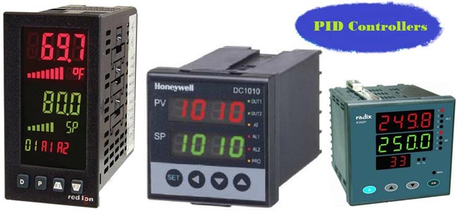
Before explaining PID Controller, let's revise about Control System. There are two types of systems; open loop system and close loop system. An open loop system is also known as an uncontrolled system and close loop system is known as a controlled system. In open loop system, the output is not controlled because this system has no feedback and in a close loop system, the output is controlled with the help of controller and this system requires one or more feedback paths. An open loop system is very simple but not useful in industrial control applications because this system is uncontrolled. Close loop system is complex but most useful for industrial application, because in this system output can be stable at a desired value, PID is an example of Closed Loop System. Block diagram of this systems is as shown in below figure-1.

A close loop system is also known as feedback control system and this type of system is used to design automatically stable system at desired output or reference. For this reason, it generates an error signal. Error signal e(t) is a difference between the output y(t) and the reference signal u(t). When this error is zero that means desired output is achieved and in this condition output is same as a reference signal.
For example, a dryer is running for a several times, which is pre-set value. When dryer is turned ON, timer starts and it will run until timer ends and give output (dry cloth). This is a simple open loop system, where output is need not to control and not require any feedback path. If in this system, we used a moisture sensor which provide feedback path and compare this with set point and generates an error. Dryer runs until this error is zero. It means when moisture of cloth is same as set point, dryer will stop working. In open loop system, dryer will run for fixed time irrespective of clothes are dry or wet. But in close loop system, dryer will not run for fixed time, it will run until clothes are dry. This is the advantage of close loop system and use of controller.
PID Controller and Its Working:
So what is PID controller? PID controller is universally accepted and most commonly used controller in industrial application because PID controller is simple, provide good stability and rapid response. PID stands for proportional, integral, derivative. In each application, coefficient of these three actions are varied to get optimal response and control. Controller input is error signal and output is given to the plant/process. Output signal of controller is generated, in such a way that, output of plant is try to achieve desired value.
PID controller is a Close loop system which has feedback control system and it compares the Process variable (feedback variable) with set Point and generates an error signal and according to that it adjusts the output of system. This process continues until this error gets to Zero or process variable value becomes equal to set point.
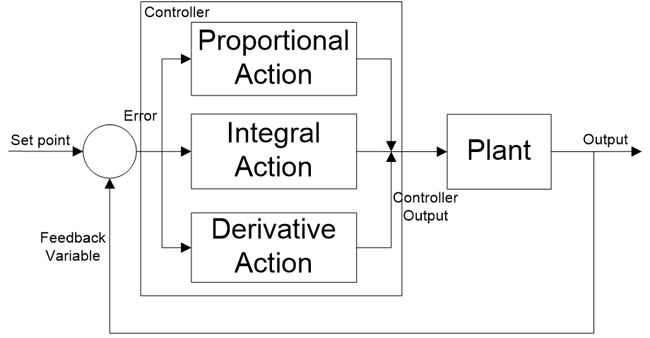
*We will learn about Proportional, Integral and Derivative actions later in this article.
PID controller gives better results than ON/OFF controller. In ON/OFF controller, only two states are available to control the system. It can either ON or OFF. It will ON when process value is less than set point and it will OFF when process value is greater than set point. In this controller, output will never be stable, it will always oscillate around the setpoint. But PID controller is more stable and precise compare to ON/OFF controller.
PID controller is a combination of three terms; Proportional, Integral and Derivative. Let us understand these three terms individually.
PID Modes of Control:
Proportional (P) response:
Term ‘P’ is proportional to the actual value of the error. If the error is large, control output is also large and if the error is small control output is also small, but gain factor (Kp) is
Also taking in to account. Speed of response is also directly proportional to proportional gain factor (Kp). So, the speed of response is increased by increasing the value of Kp but if Kp is increased beyond normal range, process variable starts oscillating at high rate and make system unstable.
y(t) ∝ e(t)
y(t) = ki * e(t)
Where Kp is proportional gain factor.
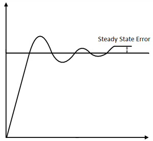
Here, the resulting error is multiplied with proportionality gain factor (proportional constant) as shown in above equation. If only P controller is used, at that time, it requires manual reset because it maintain steady state error (offset).
Integral (I) response:
Integral controller is generally used to decrease the steady state error. Term ‘I’ is integrate (with respect to time) to the actual value of the error. Because of integration, very small value of error, results very high integral response. Integral controller action continues to change until error becomes zero.
y(t) ∝ ∫ e(t)
y(t) = ki ∫ e(t)
Where Ki is a proportional gain factor.
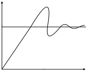
Integral gain is inversely proportional to the speed of response, increasing ki, decrease the speed of response. Proportional and Integral controllers are used combined (PI controller) for good speed of response and steady state response.
Derivative (D) response:
Derivative controller is used to with combination of PD or PID. It never used alone, because if error is constant (non-zero), output of the controller will be zero. In this situation, controller behave life zero error, but in actual there are some error (constant). Output of derivative controller is directly proportional to the rate of change of error with respect to time as shown in equation. By removing sign of proportionality, we get derivative gain constant (kd). Generally, Derivative controller is used when processor variables starts oscillating or changes at a very high rate of speed. D-controller is also used to anticipates the future behaviour of the error by error curve. Mathematical equation is as shown below;
y(t) ∝ de(t)/dt
y(t) = Kd * de(t)/dt
Where Kd is a proportional gain factor.
Proportional and Integral controller:
This is a combination of P and I controller. Output of the controller is summation of both (proportional and integral) responses. Mathematical equation is as shown in below;
y(t) ∝ (e(t) + ∫ e(t) dt)
y(t) = kp  *e(t) + ki  ∫ e(t) dt
Proportional and Derivative controller: This is a combination of P and D controller. Output of controller is summation of proportional and derivative responses. Mathematical equation of PD controller is as shown below;
y(t) ∝ (e(t) +  de(t)/dt)
y(t) = kp  *e(t) + kd  * de(t)/dt
Proportional, Integral and Derivative controller: This is a combination of P, I and D controller. Output of controller is summation of proportional, integral and derivative responses. Mathematical equation of PD controller is as shown below;
y(t) ∝ (e(t) + ∫ e(t) dt + de(t)/dt)
y(t) = kp  *e(t) + ki  ∫ e(t) dt + kd * de(t)/dt

Thus, by combining this proportional, integral and derivative control response, form a PID controller.
Tuning Methods for PID Controller:
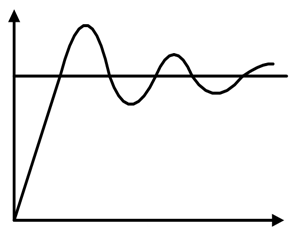
For desired output, this controller must be properly tuned. The process of getting ideal response from the PID controller by PID setting is called tuning of controller. PID setting means set the optimal value of gain of proportional (kp), derivative (kd) and integral (ki) response. PID controller is tuned for disturbance rejection means staying at a given setpoint and command tracking, means if setpoint is change, output of controller will follow new setpoint. If controller is properly tuned, output of controller will follow variable setpoint, with less oscillation and less damping.
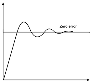
There are several methods for tuning PID controller and getting desired response. Methods for tuning controller is as below;
- Trial and error method
- Process reaction curve technique
- Ziegler-Nichols method
- Relay method
- Using software
1. Trial and error method:
Trial and error method is also known as manual tuning method and this method is simplest method. In this method, first increase the value of kp until system reaches to oscillating response but system should not make unstable and keep value of kd and ki zero. After that, set value of ki in such a way that, oscillation of system is stops. After that set the value of kd for fast response.
2. Process reaction curve technique:
This method is also known as Cohen-Coon tuning method. In this method first generate a process reaction curve in response to a disturbance. By this curve we can calculate the value of controller gain, integral time and derivative time. This curve is identified by performing manually in open loop step test of the process. Model parameter can find by initial step percentage disturbance. From this curve we have to find slop, dead time and rise time of curve which is nothing but the value of kp, ki and kd.
3. Zeigler-Nichols method:
In this method also first set the value of ki and kd zero. The proportional gain (kp) is increase until it reaches at the ultimate gain (ku). ultimate gain is nothing but it is a gain at which output of loop starts to oscillates. This ku and the oscillation period Tu are used to derive gain of PID controller from below table.
|
Type of Controller |
kp |
ki |
kd |
|
P |
0.5 ku |
|
|
|
PI |
0.45 ku |
0.54 ku/Tu |
|
|
PID |
0.60 ku |
1.2 ku/Tu |
3 kuTu/40 |
4. Relay method:
This method is also known as Astrom-Hugglund method. Here output is switched between two values of the control variable but these values are chosen in such a way that process must cross the setpoint. When process variable is less than setpoint, the control output is set to the higher value. When process value is greater than setpoint, the control output is set to the lower value and output waveform is formed. The period and amplitude of this oscillatory waveform is measured and used to determine ultimate gain ku and period Tu which is used in above method.
5. Using software:
For PID tuning and loop optimization, software packages are available. These software packages collect data and make a mathematical model of system. By this model, software finds an optimal tuning parameter from reference changes.
Structure of PID controller:
PID controllers are designed based on the microprocessor technology. Different manufactures use different PID structure and equation. Most common used PID equations are; parallel, ideal and series PID equation.
In parallel PID equation, proportional, integral and derivative actions are working separately with each other and combine effect of these three actions are act in the system. Block diagram of this type of PID is as shown below;
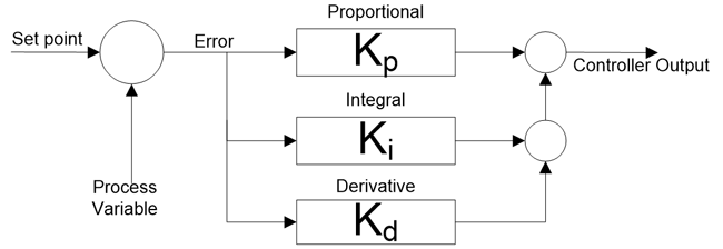
In ideal PID equation, gain constant kp is distributed to all term. So, changes in kp affects all other terms in the equation.

In series PID equation, gain constant kp is distributed to all terms same as ideal PID equation, but in this equation integral and derivative constant have an effect on proportional action.

Applications of PID controller:
Temperature control:
Let us take an example of AC (air-conditioner) of any plant/process. Setpoint is temperature (20 ͦ C) and current measured temperature by sensor is 28 ͦ C. Our aim is to run AC at desired temperature (20 ͦ C). Now, controller of AC, generate signal according to error (8 ͦ C) and this signal is given to the AC. According to this signal, output of AC is changed and temperature decrease to 25 ͦ C. further same process will repeat until temperature sensor measure desired temperature. When error is zero, controller will give stop command to AC and again temperature will increase up to certain value and again error will generate and same process repeated continuously.
Designing of MPPT (Maximum power point tracking) charge controller for solar PV:
The I-V characteristic of a PV cell depends on temperature and irradiance level. So, operating voltage and current will change continuously with respect to change in atmospheric conditions. Therefore, it is very important to track maximum power point for an efficient PV system. To find MPPT, PID controller is used and for that current and voltage setpoint is given to the controller. If atmospheric conditions will change, this tracker keeps voltage and current constant.
Power electronics converter:
PID controller is most useful in power electronics application like converters. If a converter is connected with system, according to change in load, output of converter must change. For example, an inverter is connected with load, if load increase more current will flow from inverter. So, voltage and current parameter is not fix, it will change according to requirement. In this condition, PID controller is used to generate PWM pulses for switching of IGBTs of inverter. According to change in load, feedback signal is given to controller and it will generate error. PWM pulses are generated according to error signal. So, in this condition we can get variable input and variable output with same inverter.
Very nice article, but for me
Very nice article, but for me I need a good teacher for this !
PIT CONTROLLER
I am a student of Diploma Electrical/Electronic Engineering at NORTEC in Ndola, Zambia.
I want to come up with a simple closed loop controller for a Speed Governor of a Mini Hydro Generator.
Very excellent article on…
Very excellent article on PID Control.
Thanks


Pretty good article, could have included picture of a "Eurotherm" controller (a firm that developed early PID devices), and a clear up of the odd typo. Informative though.