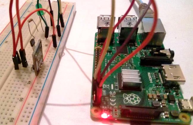
Hall sensors are sensors which produces an electrical signal at its output when it comes in contact with a magnetic field. The analog value of the electric signal at the output of the sensor is a function of the strength of the magnetic field. Hall sensors are everywhere these days, they are being used for different reasons and in all kind of devices from mobile phones to switches, for the measurement of speed, position and distance in cars and in other automotive industry based products. This versatility of hall sensor makes them a must have for makers and electrical engineers that’s why today, I will be showing us how to use a Hall Sensor in a Raspberry Pi Based Project.
You can anytime check our other Hall Sensor based projects, including interfacing of hall sensor with Arduino.
Required components
The following components/parts are required to build this project;
- Raspberry pi 2 or 3
- SD card (8gb Minimum)
- Hall Effect Sensor
- Jumper wires
- Breadboards
- LAN Cable
- Power source
Some optional parts that may be used include:
- Monitor
- Keyboard and Mouse
- HDMI cable
- Wi-Fi Dongle
This tutorial will be based on the Raspbian stretch OS, so to proceed as usual I will assume you are familiar with setting up the Raspberry Pi with the Raspbian stretch OS, and you know how to SSH into the raspberry pi using a terminal software like putty. If you have issues with any of this, there are tons of Raspberry Pi Tutorials on this website that can help.
For those who will be installing the Raspbian stretch OS for the first time, one issue I have discovered, most people have, is getting into the Raspberry Pi via ssh. It should be noted that ssh is originally disabled on the OS and you will need either a monitor to enable it, or under the raspberry pi’s configuration options or you create a blank file named ssh using your windows or Linux computer and copy the blank file to the root directory of the SD card. You will need to insert the SD cart into the SDd card slot of your computer to copy to it.
Using the second method is more suitable for those running the pi in headless mode. With all the parts ready we can then proceed to building.
Circuit Diagram:
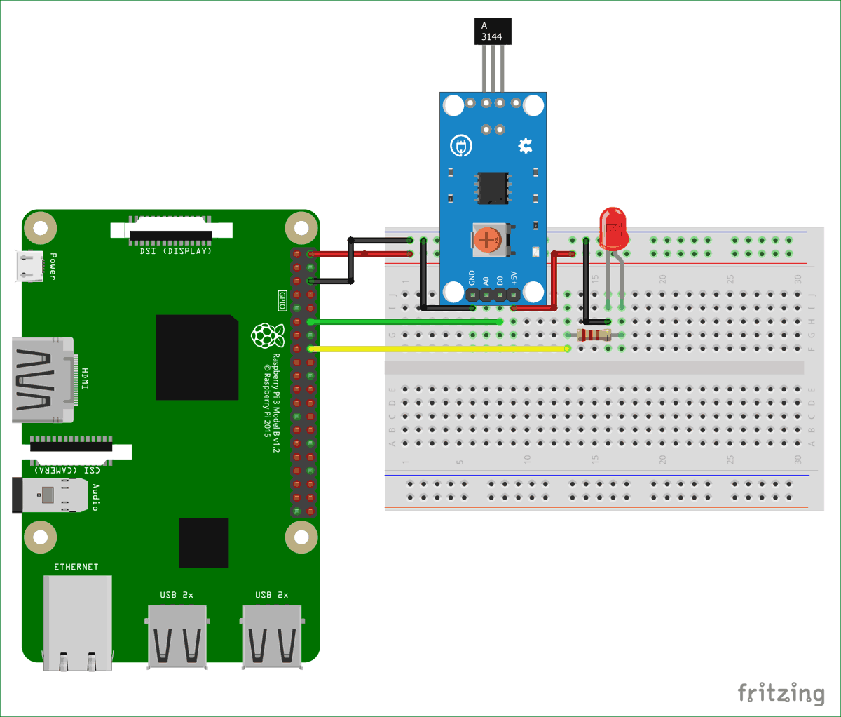
For using Hall effect sensor with Raspberry Pi, connect the components according to the schematic below.
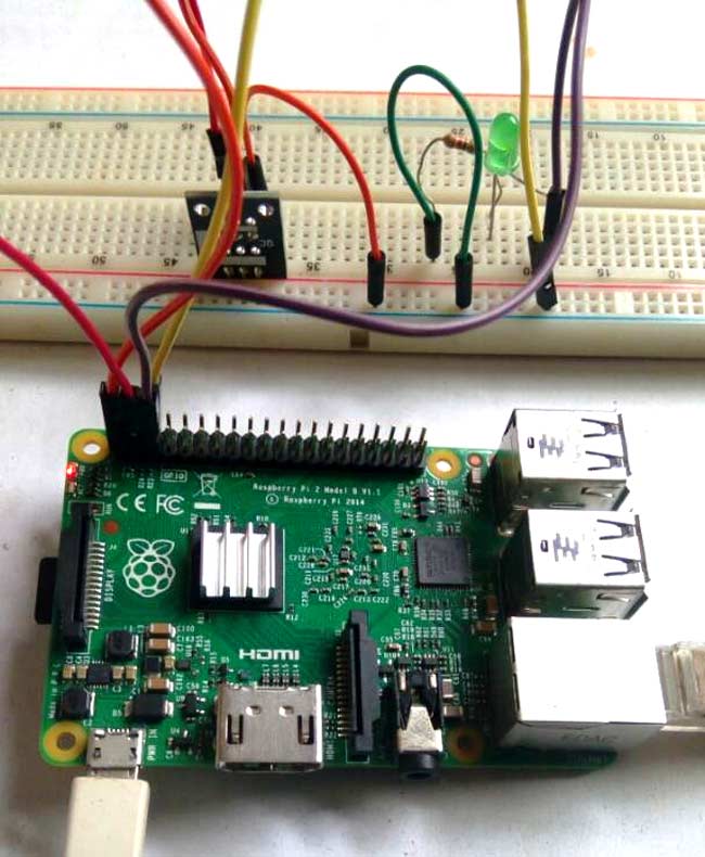
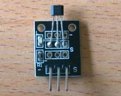
The Hall sensor used for this tutorial can provide both analog and digital values at the output. But to simplify the tutorial, I decided to use the digital value because using the analog output will require the connection of an ADC to the Raspberry Pi.
Python Code and Working Explanation:
The Python Code for this Hall Sensor project is a very simple one, all we need to do is to read the output from the hall sensor, and turn on or off the LED accordingly. The LED is to be turned on if the magnet is detected and it is to be turned off otherwise.
Power up your Raspberry Pi and SSH into it using putty (if connected in headless mode like I am). As usual with most of my projects, I create a directory inside the home directory where everything about each project is stored so for this project, we will create a directory called hall. Please note this is just a personal preference to keep things organized.
Create the directory using;
mkdir hallsensor
Change directory into the new directory just created and open an editor to create the python script using;
cd hallsensor
followed by;
nano hallsensorcode.py
Once the editor opens, we type in the code for project. I will do a brief breakdown of the code to show key concepts, and the complete python code will be made available after that.
We start the code by importing the RPI.GPIO library which allows us write python scripts to interact with the raspberry pi GPIO pins.
import RPi.GPIO as gpio
Next we set the numbering configuration for the Rpi’s GPIO that we will like to use and disable GPIO warnings to allow free flow execution of the code.
gpio.setmode(gpio.BCM)
gpio.setwarnings(False)
We then set declare the GPIO pins to which the LED and the digital output of the hall sensor is connected in accordance with the BCM numbering selected.
hallpin = 2
ledpin = 3
Next, we set up the GPIO pins as input or output. The pin with which the LED is connected set as output and the one to which the hall sensor is connected set as input.
gpio.setup( hallpin, gpio.IN)
gpio.setup(ledpin, gpio.OUT)
With that done, we write the main part of the code, which is a while loop that constantly evaluates the output from the hall sensor and turns on the LED if a magnet is detected and turns off the LED when a magnet is not detected.
while True:
    if(gpio.input(hallpin) == False):
        gpio.output(ledpin, True)
        print("magnet detected")
    else:
        gpio.output(ledpin, False)
        print("magnetic field not detected")
The complete python code with demo Video is given at the end of the project.
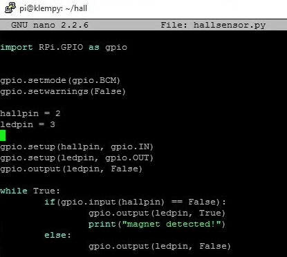
Copy and Save the code and exit the editor after typing it in using;
CTRL + X followed by y.
After saving, go over your connections once again and run the python script using;
sudo python hallsensorcode.py
With the script running, whenever a magnet or anything magnetic is brought close to the hall sensor, the LED lights up like shown in the image below.
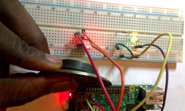
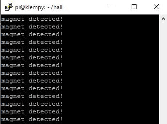
From reed switches for a smart home to speedometers for a bicycle, there are several super cool stuffs that can be built with this tutorial at the base. Feel free to share any project you plan to build in the comment section below.
All check our previous hall sensor based projects:
import RPi.GPIO as gpio
gpio.setmode(gpio.BCM)
gpio.setwarnings(False)
hallpin = 2
ledpin = 3
gpio.setup( hallpin, gpio.IN)
gpio.setup(ledpin, gpio.OUT)
gpio.output(ledpin, False)
while True:
if(gpio.input(hallpin) == False):
gpio.output(ledpin, True)
print("magnet detected")
else:
gpio.output(ledpin, False)
print("magnetic field not detected")
Comments
No it should work on all the
No it should work on all the GPIO pins are you mentioning the pin name correctly? show us the code



I'm trying to get this project to work with different GPIO pins because the ones used in this tutorial are already going to be used by the touchscreen (GPIO 2 & 3).
So far, the hall sensor only works correctly using GPIO 2 & 3, when I try other pins, it just detects magnet all the time with no magnet close by.