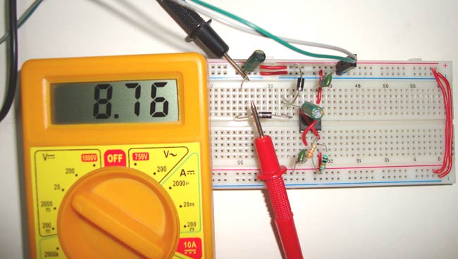
Voltage doubler is the circuit where we get the twice of the input voltage, like if we supply 5v voltage, we will get 10 volt at the output. Generally transformers are there to step-up or step-down the voltage, but sometimes transformers are not feasible because of their size and cost. So here is the quick, easy and practical solution to double the voltage, using 555 timer IC.
Components
- 555 timer IC
- Diodes -2 (1N4007)
- Resistors- 10k, 33k
- Capaciotors- 22uf (2), 0.01uF (2)
- 3-12v Power supply source
Voltage Doubler Circuit Diagram & Explanation
We can divide the circuit into two parts, first part consist the 555 time IC in Astable mode, to generate the square wave and second part consist 2 diodes and 2 capacitors to double the output voltage.
We have configured 555 Timer IC in Astable multivibrator mode to generate the square wave of approx. 2KHz, this frequency is decided by the resistor R1, R2 and capacitor C1. Below is he formulae for the same:
F = 1.44 / (R1+2*R2) * C1
When the output at PIN 3 of 555 IC is low, Diode D1 get forward biased and capacitor C3 get charged through the D1. Capacitor C3 get charged up to the same voltage at the source, in our case 5v.
Now when output at PIN 3 goes high, D1 get reverse biased and blocks the discharging of the capacitor C3, and at the same time D2 is forward biased and allow the capacitor C4 to charge. Now the capacitor C4 charges with the combined voltage of Capacitor C3 and the input source voltage, means 5v of capacitor C3 and 5v of input supply, so it charges up to 10v (twice the voltage of input source). But in practical we get output voltage less than the twice of input voltage, like in our case we get approx. 8.76v instead of 10v.
There are also some disadvantages of this voltage doubler circuit:
- However this circuit is very useful to generate higher voltage from a low power source, but this can only deliver up to 50mA current. So it should only be used for low current driven applications.
- Also the output voltage may be unstable, so a voltage regulator (IC78XX) of proper rating can be used regulation and smooth output. But voltage regulator IC itself consume some current, and reduce the deliverable current (must not exceed 70mA).
Notes:
- Input voltage should be between 3-12 volt, higher voltage will destroy the 555 timer IC.
- The load at output should not draw more than 70mA current.
- Voltage wont double instantaneously but it will increase slowly and after some time, it will set to the twice of input voltage.
- The voltage rating of capacitor C4 should be at least twice the input voltage.
- The output voltage is not exactly the twice of input voltage, it will be less than Input voltage. Like we got 8.76v for 5v input supply and if you apply 12v, output voltage would be 18-20 volt.
Comments
Please recheck your circuit
Please recheck your circuit and connections, also measure the voltage between specified points.
voltage doubler
i got more than twice for 12v input i got 27.44volts
to increase voltage which is
to increase voltage which is ic is used and we can increase
Connections
Hi
This looks like a good circuit.
I just have a couple of questions:
1. Are pin 3 and pin 7 connected between R1 and R2?
2. Is pin 6 connected to pin 1 and pin 2?
3. If so, then C1 seems to be short-circuited.
4. All the other connections have a dot to show connectivity, but not those.
Thank you
Max
Answers to your questions:
Answers to your questions:
1. No
2. Pin 6 is connected to Pin 2 but not with Pin 1.
yes you are right dots are missing at some connections.
The circuit given and the
The circuit given and the process is absolutely correct. The output received by my team was exactly double of my input voltage. Thank you.
voltage doubler circuit
dear all
anyone can show a circuit of getting 400volt DC out of an input of 220AC
Please advice with a stable and reliable circuit
This is not exactly what you
This is not exactly what you want, but this circuit may help: 12v DC to 220v AC Inverter Circuit
Where does the current flow
Where does the current flow during charging of capacitor c3. As it cannot flow into pin 3
400V from 220V
Using PFC circuits one can get stable 400V DC from 220Vac.
About application
Sir .first of all I would like to thanks to provide this circuit information
Please tell me some application where we can use this double circuit
I need a circuit that have
I need a circuit that have input 0v-10v and output have 0v-40v respectively.
thanks
Sir, can i use 47uf capacitor
Sir, can i use 47uf capacitor in place of 22uf ?
Schematic showing connection fromm pin 6 on only one side
If pin 6 is connected to pin 2, but not but not pin 1, why don't you fix it by
putting a dot where the wire from 6 meets 2. I've been reading schematics for
40 years and never had to guess what the wiring was. A little jump over symbol
where is crosses pin 1 and other cross overs would do no harm since this is for beginners. Embarrassing to be building a circuit with my grandson and be left guessing how to wire it.
Thank You, sorry to be critical.
The 555 specs say this IC…
The 555 specs say this IC can provide 200 ma to another circuit. Do resistors R1 and R2 have any effect on available power output, or do they simply determine the frequency (in conjunction with capacitor C1) and duty cycle?


i got only same input voltage. i did this multiple times.