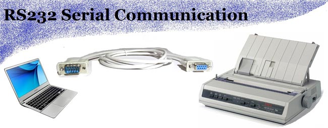
One of the oldest, yet popular communication protocol that is used in industries and commercial products is the RS232 Communication Protocol. The term RS232 stands for "Recommended Standard 232" and it is a type of serial communication used for transmission of data normally in medium distances. It was introduced back in the 1960s and has found its way into many applications like computer printers, factory automation devices etc. Today there are many modern communication protocols like the RS485, SPI, I2C, CAN etc.. you can check them out if interested. In this article, we will understand the basics of the RS232 Protocol and how it works.
What is a serial communication?
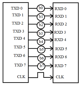
In telecommunication, the process of sending data sequentially over a computer bus is called as serial communication, which means the data will be transmitted bit by bit. While in parallel communication the data is transmitted in a byte (8 bit) or character on several data lines or buses at a time. Serial communication is slower than parallel communication but used for long data transmission due to lower cost and practical reasons.

Example to understand:
Serial communication – you are shooting a target using machine guns, where bullets reach one by one to the target.
Parallel communication- you are shooting a target using a shotgun, where many number of the bullets reach at the same time.
Modes of Data Transfer in Serial Communication:
- Asynchronous Data Transfer – The mode in which the bits of data are not synchronized by a clock pulse. Clock pulse is a signal used for synchronization of operation in an electronic system.
- Synchronous Data Transfer – The mode in which the bits of data are synchronized by a clock pulse.
Characteristics of Serial Communication:
- Baud rate is used to measure the speed of transmission. It is described as the number of bits passing in one second. For example, if the baud rate is 200 then 200 bits per Sec passed. In telephone lines, the baud rates will be 14400, 28800 and 33600.
- Stop Bits are used for a single packet to stop the transmission which is denoted as “T”. Some typical values are 1, 1.5 & 2 bits.
- Parity Bit is the simplest form of checking the errors. There are of four kinds, i.e., even odd, marked and spaced. For example, If 011 is a number the parity bit=0, i.e., even parity and the parity=1, i.e., odd parity.
What is RS232?
RS232C “Recommended Standard 232C” is the recent version of Standard 25 pin whereas, RS232D which is of 22 pins. In new PC’s male D-type which is of 9 pins.
RS232 is a standard protocol used for serial communication, it is used for connecting computer and its peripheral devices to allow serial data exchange between them. As it obtains the voltage for the path used for the data exchange between the devices. It is used in serial communication up to 50 feet with the rate of 1.492kbps. As EIA defines, the RS232 is used for connecting Data Transmission Equipment (DTE) and Data Communication Equipment (DCE).

Universal Asynchronous Data Receiver &Transmitter (UART) used in connection with RS232 for transferring data between printer and computer. The microcontrollers are not able to handle such kind of voltage levels, connectors are connected between RS232 signals. These connectors are known as the DB-9 Connector as a serial port and they are of two type’s Male connector (DTE) & Female connector (DCE).
Electrical Specifications
Let us discuss the electrical specifications of RS232 given below:
- Voltage Levels: RS232 also used as ground & 5V level. Binary 0 works with voltages up to +5V to +15Vdc. It is called as ‘ON’ or spacing (high voltage level) whereas Binary 1 works with voltages up to -5V to -15Vdc. It is called as ‘OFF’ or marking (low voltage level).
- Received signal voltage level: Binary 0 works on the received signal voltages up to +3V to +13 Vdc & Binary 1 works with voltages up to -3V to -13 Vdc.
- Line Impedances: The impedance of wires is up to 3 ohms to 7 ohms & the maximum cable length are 15 meters, but new maximum length in terms of capacitance per unit length.
- Operation Voltage: The operation voltage will be 250v AC max.
- Current Rating: The current rating will be 3 Amps max.
- Dielectric withstanding voltage: 1000 VAC min.
- Slew Rate: The rate of change of signal levels is termed as Slew Rate. With its slew rate is up to 30 V/microsecond and the maximum bitrate will be 20 kbps.
The ratings and specification changes with the change in equipment model.
How RS232 Works?
RS232 works on the two-way communication that exchanges data to one another. There are two devices connected to each other, (DTE) Data Transmission Equipment& (DCE) Data Communication Equipment which has the pins like TXD, RXD, and RTS& CTS. Now, from DTE source, the RTS generates the request to send the data. Then from the other side DCE, the CTS, clears the path for receiving the data. After clearing a path, it will give a signal to RTS of the DTE source to send the signal. Then the bits are transmitted from DTE to DCE. Now again from DCE source, the request can be generated by RTS and CTS of DTE sources clears the path for receiving the data and gives a signal to send the data. This is the whole process through which data transmission takes place.
|
TXD |
TRANSMITTER |
|
RXD |
RECEIVER |
|
RTS |
REQUEST TO SEND |
|
CTS |
CLEAR TO SEND |
|
GND |
GROUND |
For example: The signals set to logic 1, i.e., -12V. The data transmission starts from next bit and to inform this, DTE sends start bit to DCE. The start bit is always ‘0’, i.e., +12 V & next 5 to 9 characters is data bits. If we use parity bit, then 8 bits data can be transmitted whereas if parity doesn’t use, then 9 bits are being transmitted. The stop bits are sent by the transmitter whose values are 1, 1.5 or 2 bits after the data transmission.


Mechanical Specification
For mechanical specifications, we have to study about two types of connectors that is DB-25 and DB-9. In DB-25, there are 25 pins available which are used for many of the applications, but some of the applications didn’t use the whole 25 pins. So, the 9 pin connector is made for the convenience of the devices and equipments.
Now, here we are discussing the DB-9 pin connector which is used for connection between microcontrollers and connector. These are of two types: Male Connector (DTE) & Female Connector (DCE). There are 5 pins on the top row and 4 pins in the bottom row. It is often called DE-9 or D-type connector.
Pin Structure of DB-9 Connector:
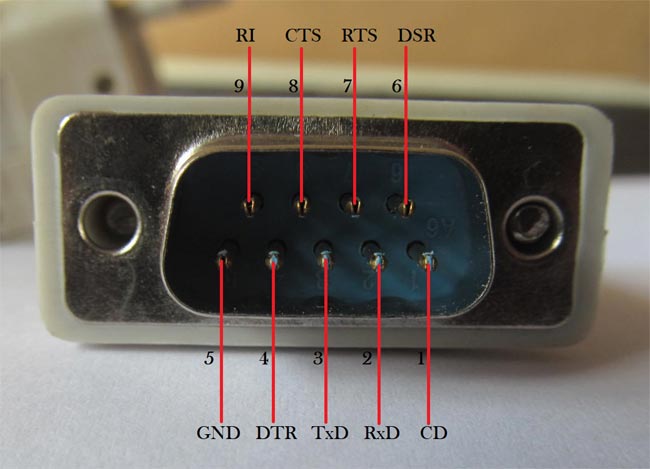
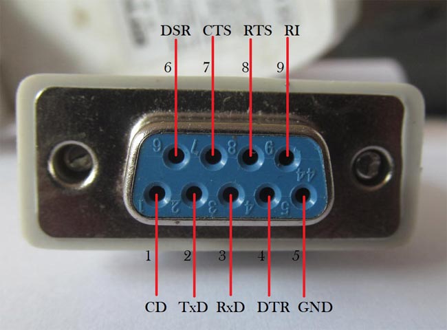
Pin Description DB-9 Connector:
|
PIN No. |
Pin Name |
Pin Description |
|
1 |
CD (Carrier Detect) |
Incoming signal from DCE |
|
2 |
RD (Receive Data) |
Receives incoming data from DTE |
|
3 |
TD (Transmit Data) |
Send outgoing data to DCE |
|
4 |
DTR (Data Terminal Ready) |
Outgoing handshaking signal |
|
5 |
GND (Signal ground) |
Common reference voltage |
|
6 |
DSR (Data Set Ready) |
Incoming handshaking signal |
|
7 |
RTS (Request to Send) |
Outgoing signal for controlling flow |
|
8 |
CTS (Clear to Send) |
Incoming signal for controlling flow |
|
9 |
RI (Ring Indicator) |
Incoming signal from DCE |
What is Handshaking?
How can a transmitter, transmits and the receiver receives data successfully. So, the Handshaking defines, for this reason.
Handshaking is the process which is used to transfer the signal from DTE to DCE to make the connection before the actual transfer of data. The messaging between transmitter & receiver can be done by handshaking.
There are 3 types of handshaking processes named as:-
No Handshaking:
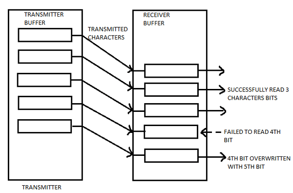
If there is no handshaking, then DCE reads the already received data while DTE transmits the next data. All the received data stored in a memory location known as receiver’s buffer. This buffer can only store one bit so receiver must read the memory buffer before the next bit arrives. If the receiver is not able to read the stored bit in the buffer and next bit arrives then the stored bit will be lost.
As shown in below diagram, a receiver was unable to read the 4th bit till the 5th bit arrival and this result overriding of 4th bit by 5th bit and 4th bit is lost.
Hardware Handshaking:
- It uses specific serial ports, i.e., RTS & CTS to control data flow.
- In this process, transmitter asks the receiver that it is ready to receive data then receiver checks the buffer that it is empty, if it is empty then it will give signal to the transmitter that I am ready to receive data.
- The receiver gives the signal to transmitter not to send any data while already received data cannot be read.
- Its working process is same as above described in handshaking.
Software Handshaking:
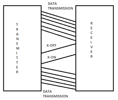
- In this process, there are two forms, i.e., X-ON & X-OFF. Here, ‘X’ is the transmitter.
- X-ON is the part in which it resumes the data transmission.
- X-OFF is the part in which it pauses the data transmission.
- It is used to control the data flow and prevent loss during transmission.
Applications of RS232 Communication
- RS232 serial communication is used in old generation PCs for connecting the peripheral devices like mouse, printers, modem etc.
- Nowadays, RS232 is replaced by advanced USB.
- It is also used in PLC machines, CNC machines, and servo controllers because it is far cheaper.
- It is still used by some microcontroller boards, receipt printers, point of sale system (PoS), etc.


There are various types of RS232 cables available in the market to convert it to other ports. Which are very usefull becuase it have solved problmens of various applications.
RS232 cables are used in the set top box , computer and weight machines and in very expensive machines too. The most widely used cable is RS232 to usb cable to communicate with other peripheral devices.