Motion detection is a common application for intruder alarms, light switches, and other home and industrial automation applications. And there are several ways to do it. We have already used a PIR sensor for motion detection, it senses the change in ambient infrared energy caused when a warm body enters the monitored area.
In this tutorial, we are going to interface RCWL-0516 Doppler Radar Sensor with Arduino Nano. The RCWL-0516 is a motion detection sensor. It can detect motion through doppler microwave technology through walls or other materials. It will get triggered not only by people but also by other moving objects. Later on, in this tutorial, we will compare the RCWL-0516 motion sensor with the PIR sensor.
Components Required
- Arduino Nano
- RCWL-0516 Doppler Radar Sensor
- LED
- 220Ω Resistor
RCWL-0516 Doppler RADAR Motion Sensor
The RCWL-0516 Doppler RADAR Motion Sensor module has been designed as an alternative to the common PIR motion sensors that are widely used by hobbyists and in burglar alarms and security lights. The PIR sensor detects motion by sniffing the black body radiation from a moving person. On the other hand, the RCWL-0516 sensor uses the Microwave Doppler radar technology to detect moving objects. The Doppler radar works by transmitting a microwave signal to a target and then analyzing the change in the frequency of the returned signal. The variation in the received signal frequency can also help measure the target’s velocity with respect to the radar.
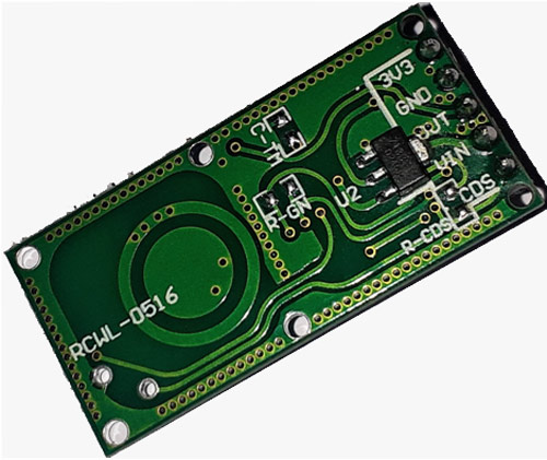
This sensor module uses an RCWL-9196 chip that supports repeat trigger and a 360-degree detection area with no blind spot. It can detect motion through walls and other materials and have a sensitivity range of 7 meters.
RCWL-0516 Sensor Pinout:
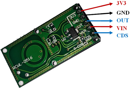
|
Pin Name |
Pin Description |
|
3V3 |
3.3V regulated output. Max 100mA |
|
GND |
Ground |
|
OUT |
Trigger: high (3.3V) if motion detected. 0V normally |
|
VIN |
4 - 28V Supply Voltage |
|
CDS |
Sensor disable input (low = disable) |
The Motion detection range and Repeat trigger time of the module can be adjusted by adding passive components in their respective solder pads located on the back of the board. There is also an option to add LDR, and a sensor disabled input pin is available to turn off the detecting function at night if necessary.
|
Pad |
Function |
|
C-TM |
Regulate the repeat trigger time. The default time is 2s. An SMD capacitor will extend the repeat trigger time. |
|
R-GN |
Detection distance adjustment. Default detection range is 7m, adding a 1M resistor reduces it to 5m |
|
R-CDS |
The VCC is in parallel connection with CDS through R-CDS. Connect the LDR at the R-CDS to turn off the detecting function at night |
RCWL-0516 Sensor Key features:
- Supply Voltage: 4–28 VDC
- Operating frequency: ~3.2 GHz
- Transmit power: 20 mW (typical)/30 mW (max)
- Sensing Distance: 5–7 m
- Output Level: 3.4V High <0.7 Low
- Output Drive: 100mA
- Output Timing: 2sec Retrigger with motion
Circuit Diagram for interfacing RCWL-0516 with Arduino
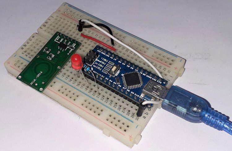
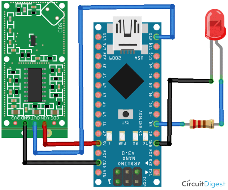
The schematic for interfacing Microwave Radar Sensor with Arduino is given below:
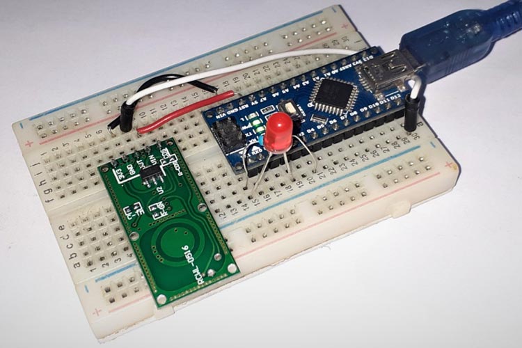
Wire up the Arduino to the RCWL-0516, and LED as shown in the diagram. The VIN and GND pin of RCWL-0516 is connected to the 5V and GND pin of Arduino Nano while the OUT pin of the sensor is connected to D12 of Nano. The LED is connected to the D3 pin of Nano.
Programming Arduino for Motion Detection using RCWL-0516 Sensor
The code for mode detection using Arduino Nano and RCWL-0516 Sensor is as simple as it gets. The complete code is given at the end of the article. The explanation of the code is as follows:
Start the code by defining all the necessary pins that are required to read the sensor data and control the LED.
int Sensor = 12;
int LED = 3;
Then inside the setup() function initialize the serial monitor at 9600 for debugging purposes. Also, set the sensor pin as input and the LED pin as output.
void setup() {
  Serial.begin(9600);
  pinMode (Sensor, INPUT);
  pinMode (LED, OUTPUT);
  Serial.println("Waiting for motion");
}
Then inside the loop() function, read the sensor pin using digitalRead() and the pin is valued greater than 0, then turn on the LED else turn off the LED.
void loop() {
     int val = digitalRead(Sensor); //Read Pin as input
     if((val > 0) && (flg==0))
     {
        digitalWrite(LED, HIGH);
        Serial.println("Motion Detected");
        flg = 1;
     }
     if(val == 0)
     {
        digitalWrite(LED, LOW);
        Serial.println("NO Motion");
        flg = 0;
     }
Testing the Motion Detection Sensor
Once your code and hardware are ready, connect Arduino to the laptop and upload the code. After that, open the serial monitor at a baud rate of 9600, and make some motion in front of the sensor. Observe LED and Serial monitor.
PIR vs. RCWL-0516 Doppler Radar Sensor
PIR detectors can detect the movement by sniffing the black body radiation from a moving person, and are ideally suited where a defined detection pattern is required, for example, a walkway. In order to have an effective coverage area, the PIR sensor must be mounted in the correct location at the right angle and can be easily misled by an attacker.
On the other hand, Microwave sensors are ideal for large spaces. Microwave sensors have a much better sensibility compared to PIR sensors. They can sometimes false trigger due to things such as trees blowing in the wind. Although, it can also detect motion through plastic, glass, and thin walls.
Most PIR sensors are affected by the climate, mostly high temperatures. The sensibility of PIR sensors is also compromised if the ambient temperature is more than 35 degrees Celsius. Microwave sensors provide more stable performance and will function at temperatures as low as -20°C and as high as 45°C. Compared to PIR sensors, microwave sensors provide a longer life cycle and can still work correctly after 100,000 hours.
All in all, both sensors are very good and at a reasonable distance. If you want an all-weather motion sensor that covers a broader area with good accuracy, then a Microwave Radar sensor is a good option.



Dabashis, thanks for this program. It is very helpful