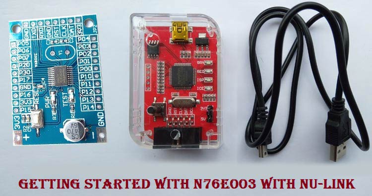
There are lots of microcontrollers available from reputed companies such as PIC, Texas Instruments, ST and the list goes on. But when we differentiate those microcontrollers with form factor vs features vs price, it gets hectic to choose one. However, nuvoton is a Taiwan based semiconductor company that was spun-off as a Winbond affiliate in 2008. The company offers very useful microcontrollers, mixed-signal chips, microprocessors with extremely high specification. But the most important thing is that it provides all features at a very low-cost margin. Thus, during the development of the production phase, the nuvoton micro-controller is getting an upper edge due to the low price and high feature supports.
For example, nuvoton N76E003 is a 20-pin microcontroller unit that supports 18 I/O pins out of 20 with features like UARTs, I2C, 6-Ch PWM, SPI, wake up functions, Brownout detectors with an 8-bit high performance 8051-based microcontroller unit. Now you should be wondering what is the price? It's less than 0.4$ (30 Rs) only. Additionally, it doesn't require an oscillator, also, since it’s equipped with 16 MHz internal RC oscillators.
In this series of tutorials, we will learn how to program the N76E003 microcontroller unit, more specifically the N76E003at20 microcontroller. Since it is a very cheaper one and has a wide range of features, you can find this microcontroller interesting if you are a beginner, or doing hobby projects or a professional one. In this specific tutorial, we will learn how to set-up the N76E003 programming environment as well as how to write the first hello world program of the embedded - blinking an LED.
Selecting the Hardware and Software Development Tools
Since the microcontroller is finalized with Nuvoton N76E003at20, it's time to find out the proper hardware and software that is required for programming the microcontroller. Let's start to find out how to create the programming environment of the N76E003.
N76E003 Development Hardware
The official development board for nuvoton N76E003 is the NuTiny-N76E003 SDK board with a programmer. But since this board is hard to find in India, and it does cost high, a standard bare minimum development board is available online. The image of the N76E003 Development board that we will use in this tutorial is shown below.
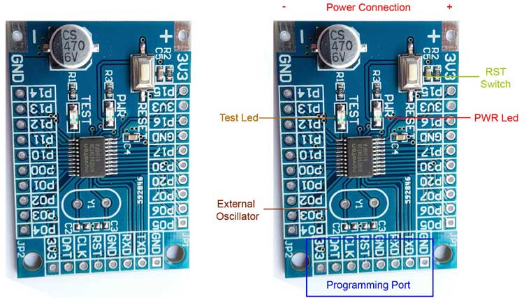
The board is just a simple development board with all pinouts from the microcontroller unit. In the below image, the internal circuit diagram for the development board is shown.
As we can see in the schematic, the development board doesn't have any kind of voltage regulator be it linear or LDO. However, it has a filter capacitor at the input. It also has a power LED and a reset button to reset the microcontroller unit. There is also a test LED available that can be configured using the code. Other than this, external crystal and required capacitors pad are also available without the components that can be very useful during further development where the external oscillator is required.
Nu-Link as N76E003 Programmer
For programming this microcontroller, we are using an unofficial Nu-link programmer which is a low cost alternative available in the online stores. However, for those who are willing to use the official Nu-link programmer, it is available for purchase as the Nu-Tiny SDK development board.
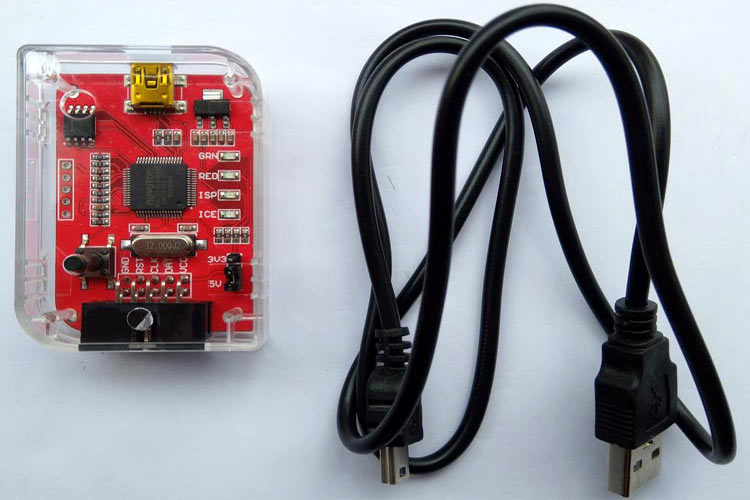
The programmer that we will use in our tutorial is shown above. It has Macro-USB connectivity, Offline programming button, and status indicator using 4 LEDs (ICE, ISP, RED, and GREEN).
IDE and Compiler for N76E003 Microcontroller
Getting the proper IDE and compiler is an important thing for any microcontroller programming. For the industry-leading microcontroller manufacturers, such as a microchip, nordic, STMicroelectronics - they all provide free c compiler and IDE. But for nuvoton programming, this is the one thing that lags. Since it is an 8051 based microcontroller, it can be programmed using Keil u vision with C51 compiler, or IAR Embedded workbench. But there is a catch. Both tools are great to do the job, but they are not free. There are trial and evaluation versions of these tools available and satisfy the job of programming nuvoton N76E003.
We have chosen Keil Micro Vision since the UI is easy to understand, good to configure and the workspace is really useful. It also comes with the C51 compiler that will compile the code for 8051 architecture.
However, to flash the program to the microcontroller, we will use the Nu-link Keil driver interface inside the Keil micro vision. This makes a one-click flash environment inside the Keil workspace. It is very useful to save time to flash the code into the chip. We will discuss more on this further.
N76E003 BSP Library
Other than the compiler and IDE, another important thing that is required for programming the N76E003 is the Board Support Package (BSP) Library. This is the Board support files for the microcontroller. This includes useful header files, peripheral libraries, SFR Macros, Hardware-level functions, etc.
So, these are my choices for Software and Hardware, let me know in the comment section if you think some other software would have been a better choice and why. I would like to explore other options as well.
Downloading Required Softwares
Now it is time to download the required files to create the environment ready for programming. Here is the list of important software that is required to be downloaded before installing anything. Just provide the required information on the Keil-C51 download page.
- Board Support Package for Keil - N76E003
- Keil Micro Vision - C51 (IDE with Compiler)
- Nu-Link Keil Driver
- Nu-Link ICP Programming Tool
Install the Keil u Vision
After downloading the Keil micro vision, install it in the default directory. It will look something similar like this-
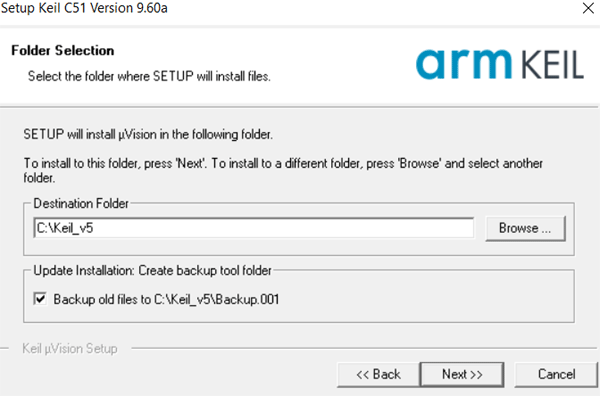
Just press the next and let it install.
Install the Nu-link Keil Driver
Open the downloaded Nu-link Keil driver. After opening the Keil driver, select the language and press next. The screen will look similar to this with the default directory automatically being set.
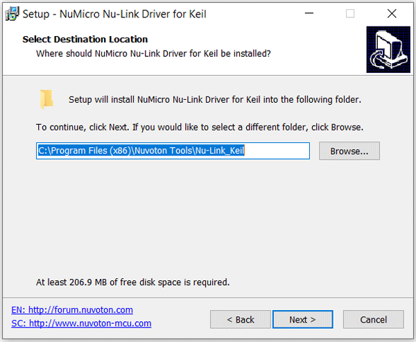
Do not change the path and press next. In this section, it will ask about the default location of Keil Microvision that was installed in the previous step.
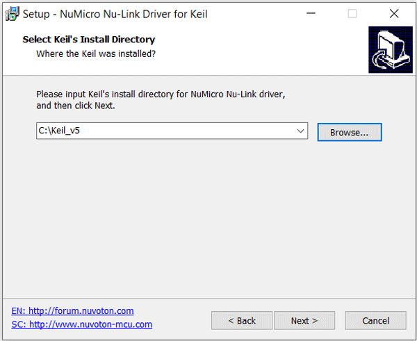
The default Keil installed location will be shown. Do not change it to anything else and press next. It will now install the Nu-Link driver for Keil. After installation is done, it will show a window like this-
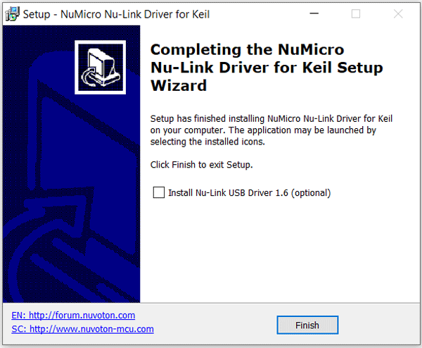
Tick the optional choice - Install Nu-Link USB Driver 1.6. Do not forget to tick this. It is not an optional thing but an important driver for the programmer and it is needed.
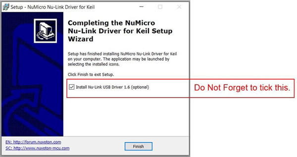
After the successful installation of the driver, it will show something like this image below-
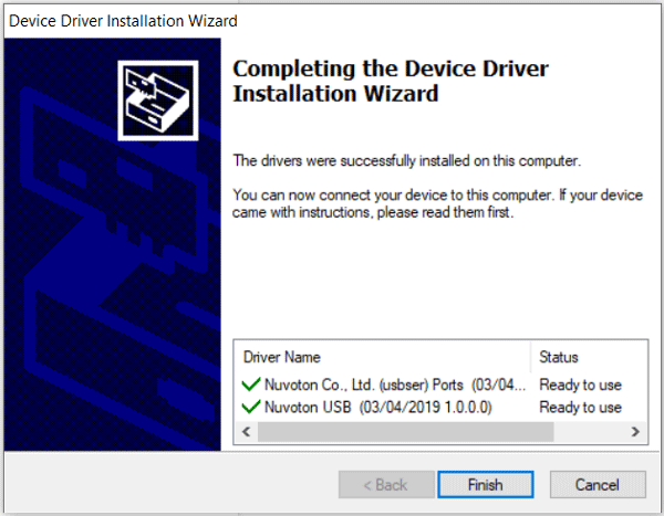
Install the Nu-link ICP Programming Tool and connect the programmer
The installation of the Nu-link ICP programming tool is pretty simple. Just use the default location and install the tool. This time, the USB driver installation option will be shown once again. There is no need to install the driver since it is already installed in the previous step.
Connect the nu-link programmer in the USB port and open the nu micro ICP Programming tool. After opening the ICP programming tool, the window will look like this-
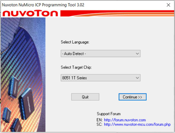
Do not change any options and press continue. The below window will open-
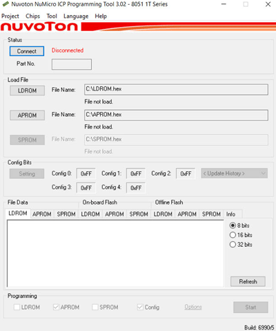
Press the connect button and if everything is alright, then the programmer tool will easily connect with the programmer.
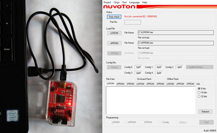
The tool will show that the programmer is connected and the green LED in the programmer will start to blink. The driver is ready and it is ready to flash the code in the N76E003 microcontroller. It is the time to set up Keil and use the Board Support Package of the N76E003.
Blink an LED on N76E003 using Keil
After extracting the board support package of the N76E003, there will be four folders - Common, Include, Sample Code, and Startup. However, the Include folder and the startup folder is what we need. Always copy this folder in the new project directory where the Keil project will be made. The Include folder has required essential hardware-based libraries that are required to compile the code.
Ok since we have all drivers installed and have the BSP files handy, let's start with our first project, blinking an LED on N76E003at20. It is a good way to test the programming environment as well as to check if everything is working. So without any delay, let's open the Keil micro vision and go to Project in the File menu bar and select a new project. It will ask for the project location.
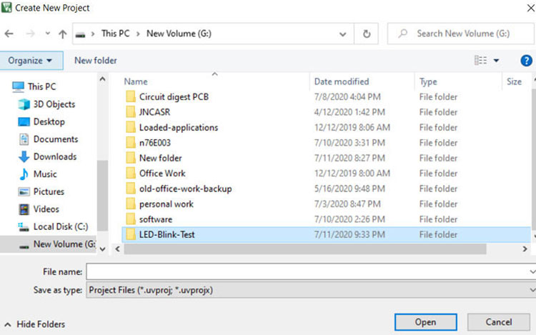
For me, Its G:/LED-Blink-Test. Choose your desired path. The window will look like this. Type “nuvoton” on the search section and select N76E003.
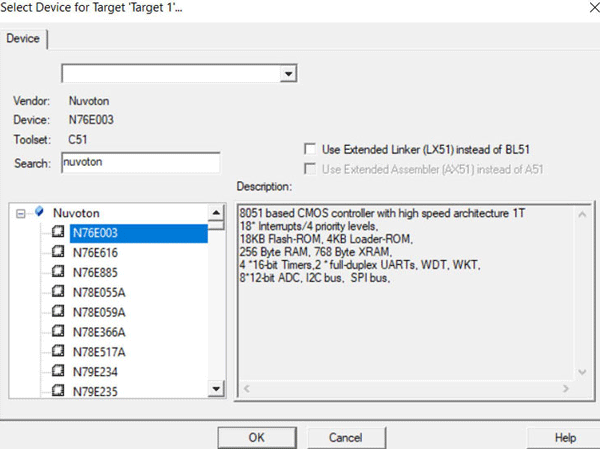
Press ok and a pop-up window will open that will ask the startup A51 configuration files to be included automatically.
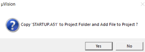
Press Yes.
The Project window will show nothing but this-

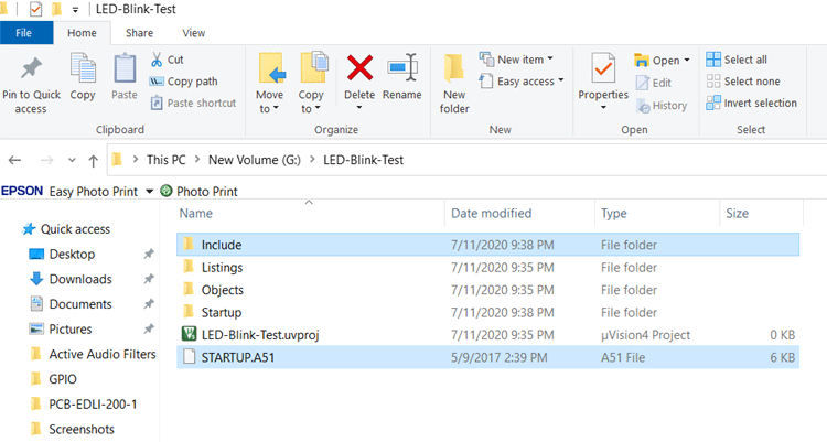
Now go to the project folder and paste the Include folder that was previously downloaded from the BSP of N76E003. Also, replace the STARTUP.A51 file with the BSP package’s STARTUP.A51 file.
Now get back to the Keil window. Select the option for Target 1.
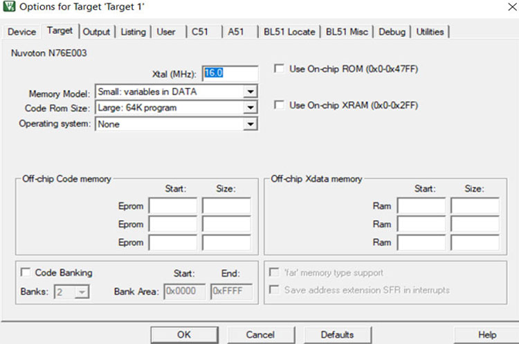
Check the crystal frequency and if it is not 16.0 MHz, then write 16.0 MHz.
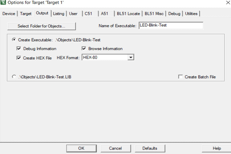
After that go to the output section. Tick the Create Hex file.
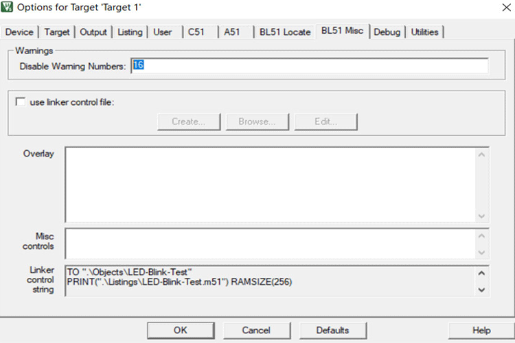
Then go to the BL51 Misc. and disable warning number 16. However, I am still not sure what warning number 16 is. If anybody has a clue, then please comment, maybe it will be discovered later. It was a default setting in the sample code provided by the nuvoton.
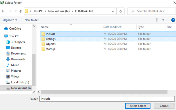
And finally, go to the C51 section and follow the consecutive images to select the include path of the BSP header files.
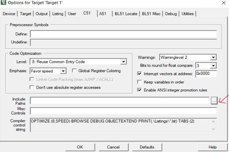
And then go to the project folder where the include folder is pasted previously.
Click on the include paths.
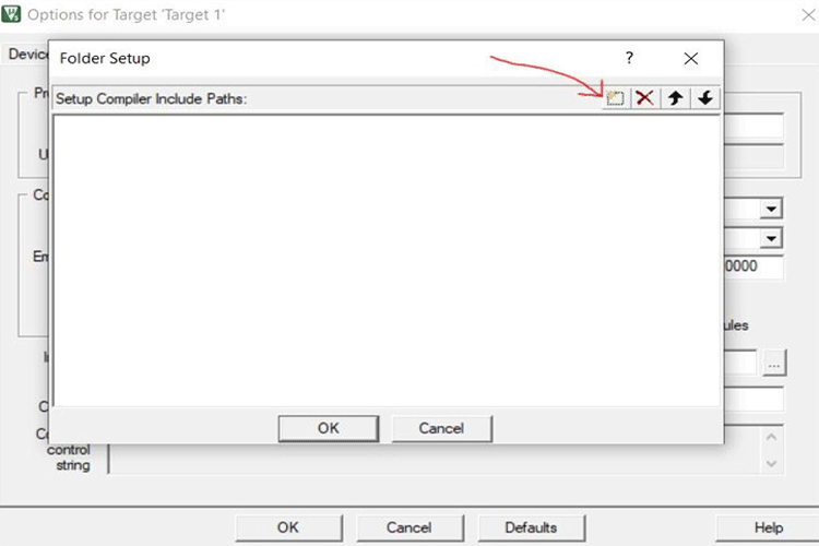
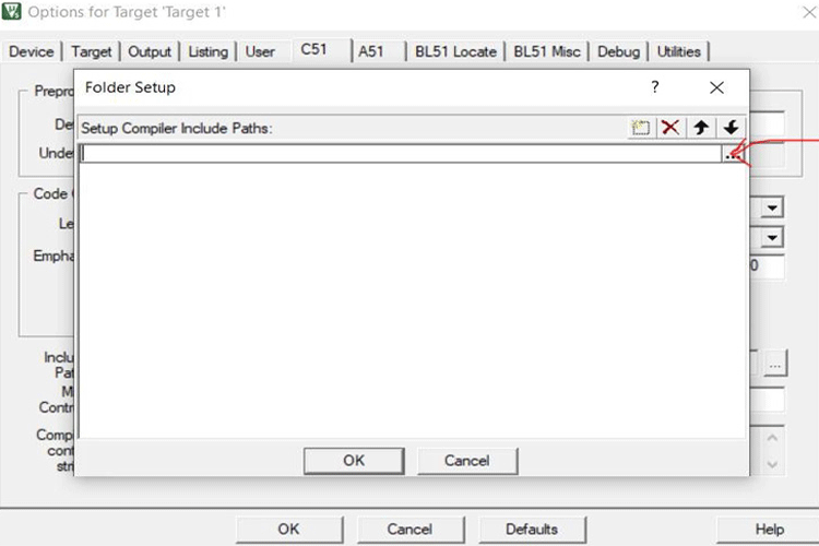
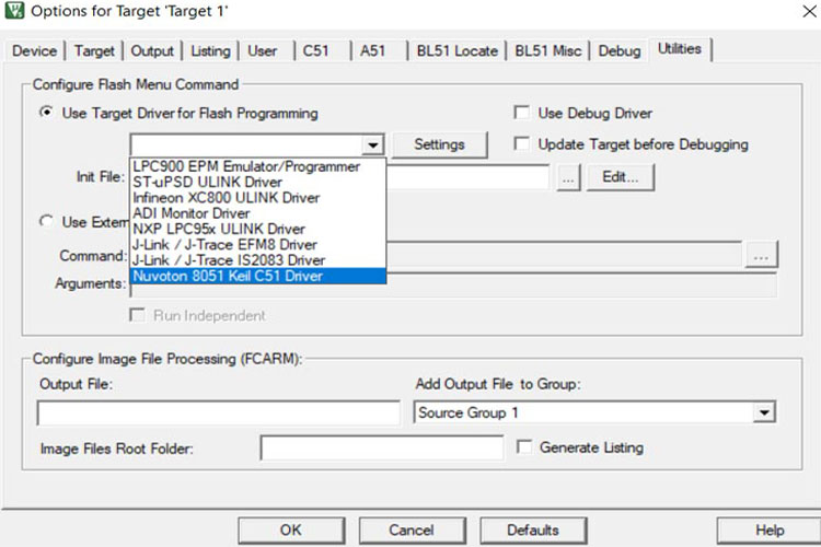
Lastly, go to the Utility and select the target driver for flash programming. Our target driver will be the Nu-Link Keil driver.
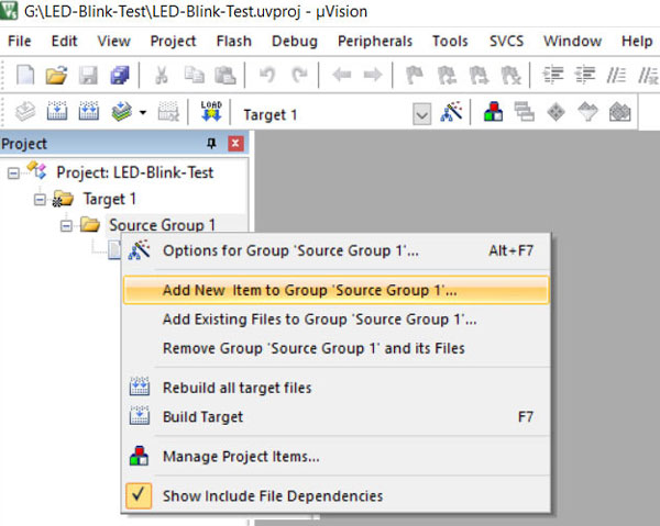
Now it's all set. Finally, Let's write the code now. Go to the source group and click add a new item to the source group.
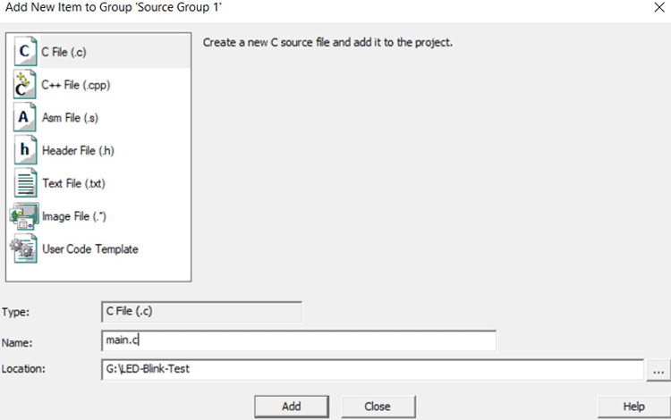
Select C file with the name main.c.
Now in the C file, write this code. We will only be testing the board and environment for now. We will get into the details of the code later.
#include "N76E003.h"
#include "SFR_Macro.h"
#include "Function_define.h"
#include "Common.h"
#include "Delay.h"
void sw_delay (int ms);
void main(void){
    P14_Quasi_Mode;
    while(1){
             P14 = 0;
             sw_delay(250);
             P14 = 1;
             sw_delay(250);
  }
}
// Software based delay. Time is not accurate.
void sw_delay (int ms){
    int a, b;
    for (a=0; a<1296; a++){
             for (b=0; b<ms; b++);
}
}
Now compile this code and it will not provide any error or warnings. The output will be-
Build started: Project: LED-Blink-Test
Build target 'Target 1'
assembling STARTUP.A51...
linking...
Program Size: data=9.0 xdata=0 code=118
creating hex file from ".\Objects\LED-Blink-Test"...
".\Objects\LED-Blink-Test" - 0 Error(s), 0 Warning(s).
Build Time Elapsed:  00:00:01
N76E003 LED Code Explanation
The code is ready to flash. Before flashing, it is important to know what is happening inside the code.
The LED is connected between the VCC supply and port 14. Therefore, to glow the LED, the P14 needs to be 0, it will sink current from the LED and the LED will glow. If P14 set to the High, the LED will be turned off since the voltage across the LED is the same.
P14_Quasi_Mode;
The above line sets P14 to Quasi mode. When the P14 is set to quasi mode, it can be only used as an IO pin. However, other than the quasi mode, each pin can also be used as Push-Pull, open drain, and Input-only mode.
void sw_delay (int ms){
    int a, b;
    for (a=0; a<1296; a++){
             for (b=0; b<ms; b++);
}
}
The above function is a software-based delay using for loop. However, it doesn’t provide accurate timing. The best way to create accurate timing is to use the timer of the microcontroller unit. Which we will learn in another tutorial.
Uploading Code on N76E003 using Nu-Link
Now, let’s flash the code into the hardware. Connect the development board with berg pins. Check the connection properly and matched it with the programmer and the development board pin names.

Connect the hardware into the PC. Make sure that the power led to the development board is glowing perfectly as shown below.
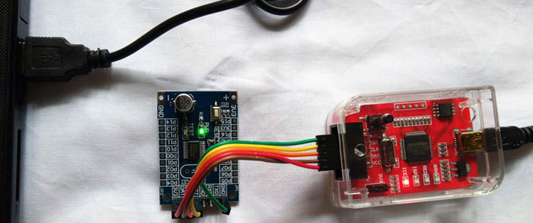
As we can see in the above image, the PWR LED is glowing in Green color. Go to the Keil compilation toolbar. Press the Build target button and the load button. You can also press the F8 button on the keyboard followed by an F7.
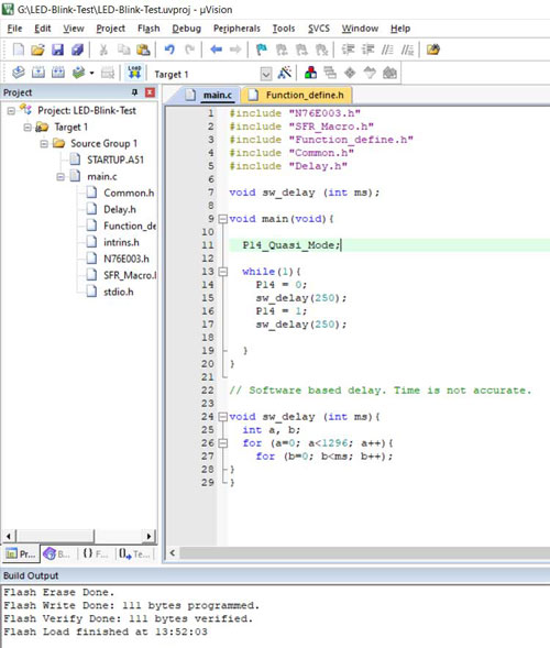
The program will be loaded in the chip and the LED will start to blink.
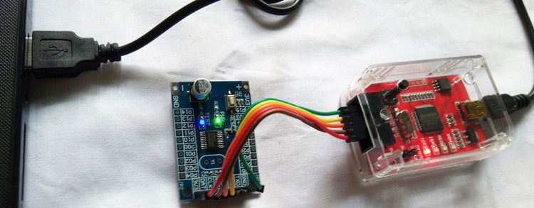
See the below video to understand the process of flashing the code in the chip. Well, this is all for the tutorial. We have learned the basics of hardware, have set up the development environment and learned how to compile and upload code. We are now ready to progress and we will be using this in all our upcoming tutorials. If you have any questions, please post them on our forums and stay tuned for more!!
#include "N76E003.h"
#include "SFR_Macro.h"
#include "Function_define.h"
#include "Common.h"
#include "Delay.h"
void sw_delay (int ms);
void main(void){
    P14_Quasi_Mode;
    while(1){
     P14 = 0;
     sw_delay(250);
     P14 = 1;
     sw_delay(250);
  }
}

// Software based delay. Time is not accurate.

void sw_delay (int ms){
    int a, b;
    for (a=0; a<1296; a++){
     for (b=0; b<ms; b++);
}Comments
Can you confirm if N76E003
Can you confirm if N76E003 will support external crystal? When we attach them on the points of Y1 as shown in picture.
Iam unable to find nu link…
Iam unable to find nu link programmer in keil settings, it is not availible in list


Thank you for usefull article. we want to create a economic version of our product and finally found Nuvoton ARM-Based microcontroller specially M4521 series that also can work with 5v. but because we dosen't have any experience with Nuvoton, it is hard to be sure about reliability. Do you have any experience with Nuvoton in industrial project?