If you are an RF Design Engineer or anyone who has worked with Wireless Radios, the term “Impedance Matching” should have struck you more than once. The term is crucial because it directly affects the transmission power and thus the range of our Radio modules. This article aims to help you understand what Impedance Matching is from basics and will also help you to design your own impedance matching circuits by using an Impedance Matching Transformer which is the most common method. So, let's dive in.
What is the Impedance Matching?
In short, Impedance matching makes sure that the output impedance of one stage, called the source, is equal to the input impedance of the following stage, called the load. This match allows for maximum power transfer and minimum loss. You can understand this concept easily by thinking about it as light bulbs in series with a power source. The first light bulb is the output impedance for stage one (a radio transmitter, for example) and the second light bulb is the load, or in other words, the input impedance of the second bulb (an antenna, for example). We want to make sure that the most power is delivered to the load, in our case, this would mean the most power is transmitted into the air so that a radio station can be heard from further away. This maximum power transfer occurs when the output impedance of the source is equal to the input impedance of the load because if the output impedance is bigger than the load more power is lost in the source (the first light bulb shines brighter).
Standing Wave Ratio – Measure of Impedance Matching
A measurement used to define how well two stages are matched is called SWR (Standing Wave Ratio). It is the ratio of the larger impedance compared to the smaller one, a 50 Ω transmitter into a 200 Ω antenna gives 4 SWR, a 75 Ω antenna feeding a NE612 mixer (input impedance is 1500 Ω) directly will an SWR of 20. A perfect match, let’s say a 50 Ω antenna and a 50 Ω receiver gives an SWR of 1.
In radio transmitters, SWRs below 1.5 are considered decent and operation when SWR is above 3 can result in damage due to overheating of the power output stage devices (vacuum tubes or transistors). In receiving applications, high SWR won’t cause damage but it will make the receiver less sensitive because the received signal will be attenuated due to mismatch and consequent power loss.
Since most receivers use some form of an input bandpass filter, the input filter can be designed to match the antenna to the input stage of the receiver. All radio transmitters have output filters that are used to match the power output stage to the specific impedance (usually 50 Ω). Some transmitters have built-in antenna tuners that can be used to match the transmitter to the antenna if the antenna’s impedance is different from the specified transmitter’s output impedance. If there is no antenna tuner, an external matching circuit has to be used. The power loss due to mismatch is hard to calculate, so special calculators or SWR loss tables are used. A typical SWR loss table is shown below
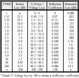
Using the SWR table above, we can calculate the power loss and also voltage loss. Voltage is lost due to mismatch when the load impedance is lower than source impedance and current is lost when the load impedance is higher than the source.
Our 50 Ω transmitter with a 200 Ω antenna with 4 SWR will lose about 36% of its power, meaning that 36% less power will be delivered to the antenna compared to if the antenna had a 50 Ω impedance. The lost power will be mostly dissipated in the source, meaning if our transmitter was giving out 100W, 36W will be additionally dissipated in it as heat. If our 50 Ω transmitter was 60% efficient, it would dissipate 66 W when transmitting 100 W into a 50 Ω antenna. When connected to the 200 Ω antenna, it will dissipate an additional 36 W so the total power lost as heat in the transmitter is 102 W. The increase of power dissipated in the transmitter not only means that full power is not being emitted by the antenna but also risk damage to our transmitter because it dissipates 102 W instead of 66W, it was designed to work with.
In the case of a 75Ω antenna, feeding the 1500Ω input of the NE612 IC, we are not concerned by power being lost as heat, but about the increased signal level that can be achieved by the use of impedance matching. Let’s say that 13nW of RF is induced in the antenna. With a 75 Ω impedance, 13nW gives 1 mV - we want to match that to our 1500 Ω load. To calculate the output voltage after the matching circuit, we need to know the ratio of impedance, in our case, 1500 Ω/75 Ω=20. The voltage ratio (like turns ratio in transformers) is equal to the square root of the impedance ratio, so √20≈8.7. This means that the output voltage will be 8.7 times bigger, so it will be equal to 8.7 mV. The matching circuits act like transformers.
Since the power entering the matching circuit and the power leaving is the same (minus loss), the output current will be lower than the input one by a factor of 8.7, but the output voltage will be bigger. If we matched a high impedance to a low one we would get lower voltage but a higher current.
Impedance Matching Transformers
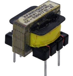
Special Transformers called Impedance Matching Transformers can be used to match impedance. The main advantage of transformers as impedance matching devices is that they have broadband, meaning they can work with a wide range of frequencies. Audio transformers using sheet steel cores, such as those used in vacuum tube amplifier circuits to match the high impedance of the tube to the low impedance of the speaker, have a bandwidth of 20Hz to 20kHz, RF transformers made using ferrite or even air cores can have bandwidths of 1MHz-30MHz.
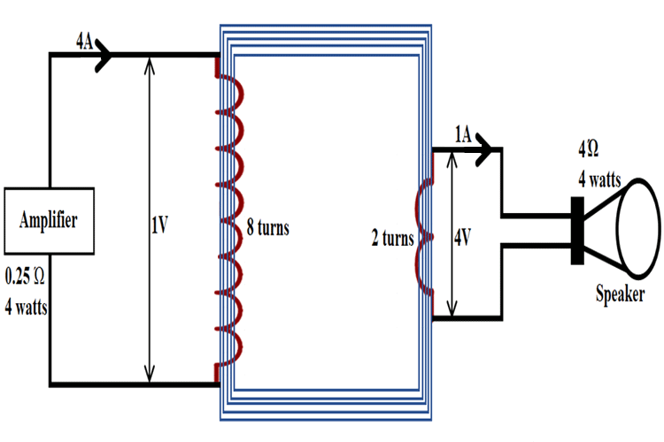
Transformers can be used as impedance matching devices, because of their turns ratio that changes the impedance that the source “sees”. You can also check this basic of the transformer article if you are completely new to transformers. If we have a transformer with a 1:4 turns ratio, this means that if 1V of AC was applied to the primary, we would have 4V of AC on the output. If we add a 4Ω resistor to the output, 1A of current will flow in the secondary, the current in the primary is equal to the secondary current multiplied by the turn’s ratio (divided if the transformer was of a step-down type, like mains transformers), so 1A*4=4A. If we use Ω’s law to determine the impedance that the transformer presents to the circuit we have 1V/4A=0.25Ω, while we connected a 4Ω load after the matching transformer. The impedance ratio is 0.25Ω to 4Ω or also 1:16. It can be also calculated with this Impedance Ratio formula:
(nA/nB)²=ri
where nA is the number of primary turns on the winding with more turns, nB is the number of turns on the winding with less turns, and ri is the impedance ratio. This is how impedance matching happens.

If we used Ohms law again, but now to calculate the power that flows into the primary we would have 1V*4A=4W, in the secondary, we would have 4V*1A=4W. This means that our calculations are correct, that transformers and other impedance matching circuits don’t give more power than they are fed. No free energy here.

How to select an Impedance Matching Transformer
Transformer matching circuit can be used when bandpass filtering is needed, is should be resonant with the inductance of secondary at the frequency of use. The main parameters of transformers as impedance matching devices are:
- Impedance ratio or more commonly stated turns ratio (n)
- Primary inductance
- Secondary inductance
- Primary impedance
- Secondary impedance
- Self-resonant frequency
- Minimum frequency of operation
- Maximum frequency of operation
- Winding configuration
- Presence of air gap and max. DC current
- Max. power
The primary turns number should be enough, so the primary winding of the transformer has reactance (it is a coil) four times the output impedance of the source at the lowest frequency of operation.
The secondary turns number is equal to the number of turns on the primary, divided by the square root of the impedance ratio.
We also need to know what core type and size to use, different cores work good in different frequencies, outside of which they exhibit loss.
Core size depends on the power flowing through the core, as each core exhibits losses and bigger cores can dissipate these losses better and not exhibit magnetic saturation and other unwanted things as easily.
An air gap is required when a DC current will flow through any winding on the transformer if the core used is made from steel laminations, like in a mains transformer.
Transformer Matching Circuits - Example
For example, we need a transformer to match a 50 Ω source to a 1500 Ω load in the frequency range of 3MHz to 30MHz in a receiver. We first need to know what core we would need since it is a receiver very little power will flow through the transformer, so core size can be small. A good core in this application would be the FT50-75. According to the manufacturer, it’s frequency range as a wideband transformer is 1MHz to 50MHz, good enough for this application.
Now we need to calculate the primary turns, we need the primary reactance to by 4 times higher than the source output impedance, so 200 Ω. At the minimum operating frequency of 3MHz, an inductor of 10.6uH has 200 Ω of reactance. Using an online calculator we calculate that we need 2 turns of wire on the core to get 16uH, a bit above 10.6uH, but in this case, it is better for it to be bigger than to be smaller. 50 Ω to 1500 Ω gives an impedance ratio of 30. Since the turns ratio is the square root of the impedance ratio we get around 5.5, so for each primary turn we need 5.5 secondary turns to make the 1500Ω at the secondary look like 50Ω to the source. Since we have 2 turns on the primary we need 2*5.5 turns on the secondary, that is 11 turns. The diameter of the wire should follow the 3A/1mm2 rule (maximum of 3A flowing per each square millimeter of wire cross-section area).
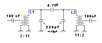
Transformer matching is often used in bandpass filters, to match resonant circuits to low impedances of antennas and mixers. The higher the impedance loading the circuit, the lower the bandwidth and the higher Q. If we connected a resonant circuit directly to a low impedance the bandwidth would be very often too large to be useful. The resonant circuit consists of the secondary of L1 and the first 220 pF capacitor and the primary of L2 and the second 220 pF capacitor.
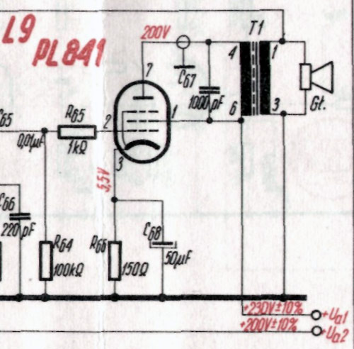
The above image shows a Transformer matching used in a vacuum tube audio power amplifier to match the 3000 Ω output impedance of the PL841 tube to a 4 Ω speaker. 1000 pF C67 prevents ringing at higher audio frequencies.
Autotransformer matching for Impedance balance
The autotransformer matching circuit is a variant of the transformer matching circuit, where the two windings are connected together on top of each other. It is commonly used in IF filter inductors, together with transformer matching to the base, where it is used to match the lower impedance of the transistor to a high impedance that loads the tuning circuit less and allows for smaller bandwidth and therefore greater selectivity. The process for designing them is practically the same, with the number of turns on the primary being equal to the number of turns from the tap of the coil to the “cold” or grounded end and the number of turns on the secondary being equal to the number of turns between the tap and the “hot” end or the end that is connected to the load.
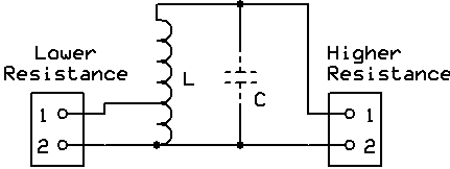
The above image shows an Autotransformer matching circuit. C is optional if used it should be resonant with the inductance of L at the frequency of use. This way the circuit also provides filtering.
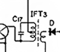
This image illustrates an Autotransformer and transformer matching used in an IF transformer. Autotransformer’s high impedance connects to C17, this capacitor forms a resonant circuit with the whole winding. Since this capacitor connects to the high impedance end of the autotransformer, the resistance loading the tuned circuit is higher, therefore circuit Q is larger and IF bandwidth is reduced, improving selectivity and sensitivity. Transformer matching couples the amplified signal to the diode.
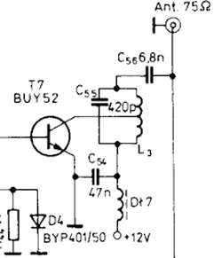
Autotransformer matching used in a transistor power amplifier, it matches the 12 Ω output impedance of transistor to the 75 Ω antenna. C55 is connected in parallel to the high impedance end of the autotransformer forms a resonant circuit that filters out harmonics.


Unfortunately, these drawings are wrong and the transformer is the wrong way around for the values stated.
A signal of 4V primary voltage (1A) will lead to 1V secondary voltage (4A), if the winding ratio is 8:2 (primary:secondary). The voltage transforms like the winding ratio. The current transfroms like the inverse of the winding ratio! The impedance will therefore transform like the square of the winding ratio.