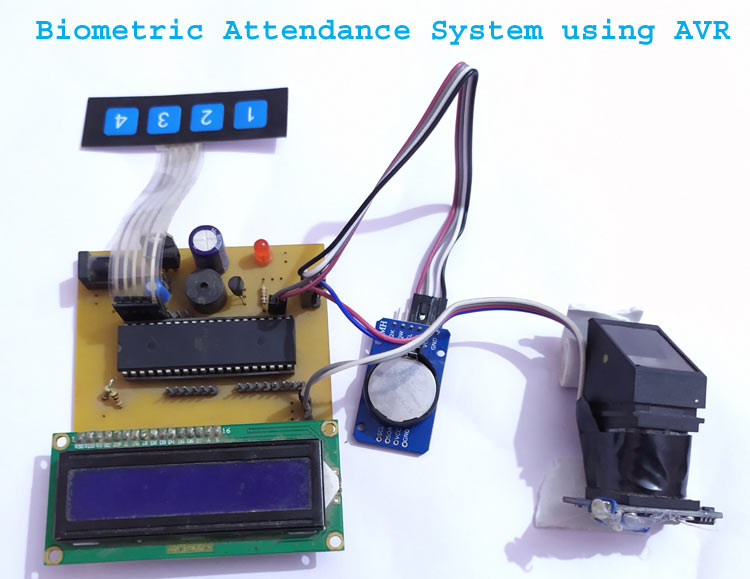
According to researchers from Pen state University, humans are more likely to trust machines over people, which is likely evident from us revealing our ATM pin to a machine so easily. Today, in the world where AI, Machine learning, Chat bots, Smart Speakers, Robots etc are actively progressing, this synergy between humans and robots is only set to increase. Today, from bridge toll collectors to check-out cashiers everything around us is being replaced by machines to get the work done easier and more efficient. To keep up with the phase, in this project we will build a Bio-metric Attendance system using AVR microcontrollers to replace the manual procedure of taking attendance. This system will be more reliable and efficient since it would save time and avoid dodgers.
Fingerprint attendance systems are already readily available directly from the market, but what is more fun than building one? We have also built a wide variety of Attendance Systems earlier from a simple RFID based Attendance system to an IoT based biometric Attendance system using Arduino and Raspberry Pi. In this project, we have used fingerprint Module and AVR(atmega32) to register attendance. By using fingerprint sensor, the system will become more secure for the users. Following sections explains technical details of making a fingerprint-based Biometric Attendance System using AVR.
Required Components
- Atmega32 -1
- Fingerprint module (r305) -1
- Push Button or membrane buttons - 4
- LEDs -2
- 1K Resistor -2
- 2.2K resistor -1
- Power 12v adaptor
- Connecting wires
- Buzzer -1
- 16x2 LCD -1
- PCB or Bread Board
- RTC Module (ds1307 or ds3231)-1
- LM7805 -1
- 1000uf, 10uf capacitor -1
- Burgstips male female
- DC JACK (optional)
- BC547 Transistor -1
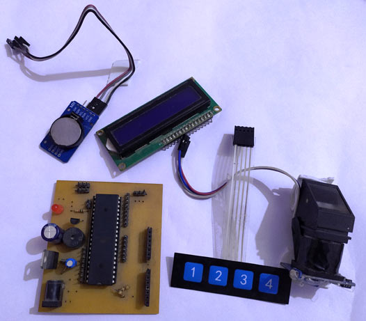
In this fingerprint attendance system circuit, we have used the Fingerprint Sensor module to authenticate a person or employee’s identity by taking their finger-print input in the system. Here we are using 4 push buttons to enroll, Delete, Increment and Decrement finger-print data. Key 1 is used for enrollment of a new person into the system. So when the user wants to enroll a new finger, then he/she need to press key 1 then LCD asks him/her to place a finger on fingerprint sensor two times then it asks for an employee ID. Similarly, key 2 has double function, like when user enrolls new finger, then he/she need to select finger-print ID by using another two keys namely 3 and 4. Now user need to press key 1 (this time this key behave like OK) to proceed with selected ID. And key 2 is also used for reset or delete data from EEPROM of microcontroller.
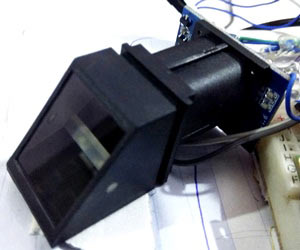
Fingerprint sensor module captures finger’s print image and then converts it into the equivalent template and saves them into its memory as per selected ID by microcontroller. All the process is commanded by the microcontroller, like taking an image of finger’s print; convert it into templates and storing as ID etc. You can also check out these other finger print sensor projects, where we have built finger print sensor security system and fingerprint sensor voting machine.
Circuit Diagram
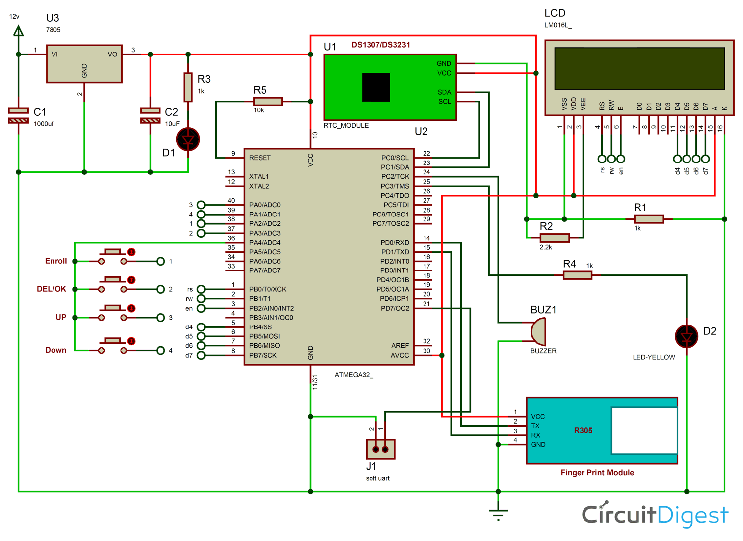
The complete circuit diagram for fingerprint based attendance system project, is shown below. It has Atmega32 microcontroller for controlling all the process of the project. The push or membrane button is used for enrolling, deleting, selecting IDs for attendance, a buzzer is used for indication and a 16x2 LCD to instruct user on how to use the machine.
As shown in the circuit diagram, push or membrane buttons are directly connected to pin PA2 (ENROL key 1), PA3(DEL key 2), PA0(UP key 3), PA1(DOWN key 4) of microcontroller with respect to the ground or PA4. And a LED is connected at pin PC2 of microcontroller with respect to ground through a 1k resistor. Fingerprint module’s Rx and Tx directly connected at Serial pin PD1 and PD3 of microcontroller. 5v supply is used for powering the whole circuit by using LM7805 voltage regulator which is powered by 12v dc adaptor. A buzzer is also connected at pin PC3. A 16x2 LCD is configured in 4-bit mode and its RS, RW, EN, D4, D5, D6, and D7 are directly connected at pin PB0, PB1, PB2, PB4, PB5, PB6, PB7 of microcontroller. RTC module is connected at I2Cpin PC0 SCL and PC1 SDA. And PD7 is used as soft UART Tx pin for getting the current time.
How Fingerprint Attendance System works
Whenever user place his finger over fingerprint module then fingerprint module captures finger image, and search if any ID is associated with this fingerprint in the system. If fingerprint ID is detected then LCD will show Attendance registered and in the same time buzzer will beep once.
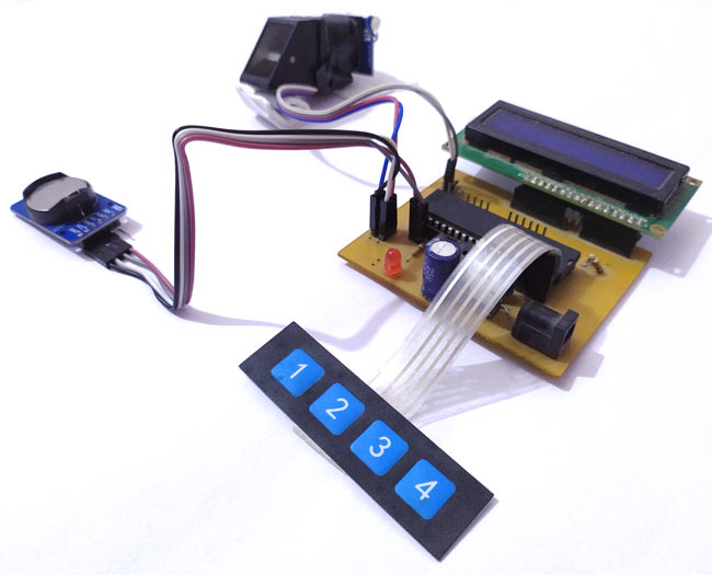
Along with the fingerprint module, we have also used an RTC module for Time and date data. Time and date are running continuously in the system, so Microcontroller can take time and date whenever a true user places his finger over fingerprint sensor and then save them in the EEPROM at the allotted slot of memory.
User may download the attendance data by pressing and holding key 4. Connect supply to circuit and wait and after some time, LCD will show ‘Downloading....’. And user can see the attendance data over serial monitor, here in this code software UART is programmed at pin PD7-pin20 as Tx to send data to terminal. User also needs a TTL to USB converter to see the attendance data over serial terminal.
And if the user wants to delete all the data then he/she has to press and hold key 2 and then connect power and wait for some time. Now after some time LCD will show ‘Please wait…’ and then ‘Record Deleted successfully’. These two steps are not shown in demonstration video given in the end.
Code Explanation
Complete code along with the video for this biometric attendance system is given at the end. Code of this project is a little bit lengthy and complex for beginner. Hence we have tried to take descriptive variables to make good readability and understanding. First of all, we have included some necessary header file then written macros for different-different purpose.
#define F_CPU 8000000ul
#include <avr/io.h>
#include <util/delay.h>
#include <avr/interrupt.h>

/***MACROS*/

#define USART_BAUDRATE 9600
#define BAUD_PRESCALE (((F_CPU / (USART_BAUDRATE * 16UL))) - 1)

#define uchar unsigned char
#define uint unsigned int

#define LCDPORTDIR DDRB
#define LCDPORT PORTB
#define rs 0
#define rw 1
#define en 2

#define RSLow (LCDPORT&=~(1<<rs))
#define RSHigh (LCDPORT|=(1<<rs))
#define RWLow (LCDPORT&=~(1<<rw))
#define ENLow (LCDPORT&=~(1<<en))
#define ENHigh (LCDPORT|=(1<<en))

#define KeyPORTdir DDRA
#define key PINA
#define KeyPORT PORTA
After this, we have declared some variables and arrays for fingerprint command and response. We have also added some functions for fetching and setting data to RTC.
void RTC_stp()
{
TWCR=(1<<TWINT)|(1<<TWEN)|(1<<TWSTO);           //stop communication
}

void RTC_read()
{
TWCR=(1<<TWINT)|(1<<TWSTA)|(1<<TWEN);
while((TWCR&0x80)==0x00);
TWDR=0xD0;                                         //RTC write (slave address)
TWCR=(1<<TWINT)|(1<<TWEN);
while(!(TWCR&(1<<TWINT)));
TWDR=0x00;                                         //RTC write (word address)
TWCR=(1<<TWINT)|(1<<TWEN);
while(!(TWCR&(1<<TWINT)));
TWCR=(1<<TWINT)|(1<<TWSTA)|(1<<TWEN);              //start RTC  communication again
while ((TWCR&0x80)==0x00);
TWDR=0xD1;                                        // RTC command to read
TWCR=(1<<TWINT)|(1<<TWEN);
while(!(TWCR&(1<<TWINT)));
}
Then we have some functions for LCD which are responsible to drive the LCD. LCD driver function is written for 4-bit mode drive. Followed by that we also have some UART driver functions which are responsible for initializing UART and exchanging data between fingerprint sensor and microcontroller.
void serialbegin()
{
  UCSRC = (1 << URSEL) | (1 << UCSZ0) | (1 << UCSZ1);
  UBRRH = (BAUD_PRESCALE >> 8);
  UBRRL = BAUD_PRESCALE;
  UCSRB=(1<<RXEN)|(1<<TXEN)|(1<<RXCIE);
  sei();
}

ISR(USART_RXC_vect)
{
char ch=UDR;
buf[ind++]=ch;
if(ind>0)
flag=1;
//serial1Write(ch);
}

void serialwrite(char ch)
{
while ((UCSRA & (1 << UDRE)) == 0);
UDR = ch;
}

void serialprint(char *str)
{
    while(*str)
    {
        serialwrite(*str++);
    }
}
Now we have some more UART function but they are software UART. It is used for transferring saved data to the computer via serial terminal. These functions are delay-based and don’t use any type of interrupt. And for UART only tx signal will work and we have hardcoded baud rate for soft UART as 9600.
void SerialSoftWrite(char ch)
{
PORTD&=~(1<<7);
_delay_us(104);
for(int i=0;i<8;i++)
{
if(ch & 1)
PORTD|=(1<<7);
else
PORTD&=~(1<<7);
_delay_us(104);
ch>>=1;
}
PORTD|=(1<<7);
_delay_us(104);
}

void SerialSoftPrint(char *str)
{
while(*str)
{
SerialSoftWrite(*str);
str++;
}
}
Followed by that we have functions that are responsible for displaying the RTC time in the LCD. The below given functions are used for writing attendance data to EEPROM and reading attendance data from EEPROM.
int eeprom_write(unsigned int add,unsigned char data)
{
while(EECR&(1<<EEWE));
EEAR=add;
EEDR=data;
EECR|=(1<<EEMWE);
EECR|=(1<<EEWE);
return 0;
}
char eeprom_read(unsigned int add)
{
while(EECR & (1<<EEWE));
EEAR=add;
EECR|=(1<<EERE);
return EEDR;
}
The below function is responsible for reading fingerprint image and convert them in template and matching with already stored image and show result over LCD.
void matchFinger()
{
    //  lcdwrite(1,CMD);
    //  lcdprint("Place Finger");
    //  lcdwrite(192,CMD);
    //  _delay_ms(2000);
     if(!sendcmd2fp((char *)&f_detect[0],sizeof(f_detect)))
     {
         if(!sendcmd2fp((char *)&f_imz2ch1[0],sizeof(f_imz2ch1)))
         {
            if(!sendcmd2fp((char *)&f_search[0],sizeof(f_search)))
            {
LEDHigh;
buzzer(200);
                uint id= data[0];
                     id<<=8;
                     id+=data[1];
                uint score=data[2];
                        score<<=8;
                        score+=data[3];
                (void)sprintf((char *)buf1,"Id: %d",(int)id);
                lcdwrite(1,CMD);
                lcdprint((char *)buf1);
saveData(id);

_delay_ms(1000);
lcdwrite(1,CMD);
lcdprint("Attendance");
lcdwrite(192,CMD);
lcdprint("Registered");
_delay_ms(2000);
LEDLow;
            }
Followed by that we have a function that is used for enrolling a new finger and displaying the result or status on LCD. Then the below function is used for deleting stored fingerprint from the module by using id number and show status of the same.
void deleteFinger()
{
    id=getId();
   f_delete[10]=id>>8 & 0xff;
   f_delete[11]=id & 0xff;
   f_delete[14]=(21+id)>>8 & 0xff;
   f_delete[15]=(21+id) & 0xff;
   if(!sendcmd2fp(&f_delete[0],sizeof(f_delete)))
  {
     lcdwrite(1,CMD);
     sprintf((char *)buf1,"Finger ID %d ",id);
     lcdprint((char *)buf1);
     lcdwrite(192, CMD);
     lcdprint("Deleted Success");

  }
   else
   {
       lcdwrite(1,CMD);
       lcdprint("Error");
   }
   _delay_ms(2000);
}
Below function is responsible for sending attendance data to serial terminal via soft UART pin PD7 and TTL to USB converter.
/*function to show attendence data on serial moinitor using softserial pin PD7*/
void ShowAttendance()
{
char buf[128];
lcdwrite(1,CMD);
lcdprint("Downloding....");
SerialSoftPrintln("Attendance Record");
SerialSoftPrintln(" ");
SerialSoftPrintln("S.No        ID1            ID2            Id3            ID4            ID5    ");
//serialprintln("Attendance Record");
//serialprintln(" ");
//serialprintln("S.No            ID1                     ID2                     Id3                     ID4                     ID5");
for(int cIndex=1;cIndex<=8;cIndex++)
{
sprintf((char *)buf,"%d    "
"%d:%d:%d  %d/%d/20%d    "
"%d:%d:%d  %d/%d/20%d    "
"%d:%d:%d  %d/%d/20%d    "
"%d:%d:%d  %d/%d/20%d    "
"%d:%d:%d  %d/%d/20%d    ",
cIndex,
eeprom_read((cIndex*6)),eeprom_read((cIndex*6)+1),eeprom_read((cIndex*6)+2),eeprom_read((cIndex*6)+3),eeprom_read((cIndex*6)+4),eeprom_read((cIndex*6)+5),
eeprom_read((cIndex*6)+48),eeprom_read((cIndex*6)+1+48),eeprom_read((cIndex*6)+2+48),eeprom_read((cIndex*6)+3+48),eeprom_read((cIndex*6)+4+48),eeprom_read((cIndex*6)+5+48),
eeprom_read((cIndex*6)+96),eeprom_read((cIndex*6)+1+96),eeprom_read((cIndex*6)+2+96),eeprom_read((cIndex*6)+3+96),eeprom_read((cIndex*6)+4+96),eeprom_read((cIndex*6)+5+96),
eeprom_read((cIndex*6)+144),eeprom_read((cIndex*6)+1+144),eeprom_read((cIndex*6)+2+144),eeprom_read((cIndex*6)+3+144),eeprom_read((cIndex*6)+4+144),eeprom_read((cIndex*6)+5+144),
eeprom_read((cIndex*6)+192),eeprom_read((cIndex*6)+1+192),eeprom_read((cIndex*6)+2+192),eeprom_read((cIndex*6)+3+192),eeprom_read((cIndex*6)+4+192),eeprom_read((cIndex*6)+5+192));


SerialSoftPrintln(buf);
//serialprintln(buf);
}
lcdwrite(192,CMD);
lcdprint("Done");
_delay_ms(2000);
}
Below function is used for deleting all the attendance data from the microcontroller’s EEPROM.
void DeleteRecord()
{
lcdwrite(1,CMD);
lcdprint("Please Wait...");
for(int i=0;i<255;i++)
eeprom_write(i,10);
_delay_ms(2000);
lcdwrite(1,CMD);
lcdprint("Record Deleted");
lcdwrite(192,CMD);
lcdprint("Successfully");
_delay_ms(2000);
}
In the main function we will initialize all the used module and gpio pins. Finally, all-controlling event are performed in this as shown below
while(1)
  {
    RTC();

  //  if(match == LOW)
   // {
matchFinger();
   // }

    if(enrol == LOW)
    {
buzzer(200);
        enrolFinger();
        _delay_ms(2000);
       // lcdinst();
    }

    else if(delet == LOW)
    {
buzzer(200);
        getId();
        deleteFinger();
        _delay_ms(1000);
    }
  }
  return 0;
}
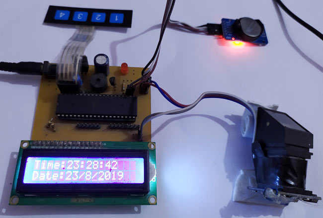
The complete working set-up is shown in the video linked below. Hope you enjoyed the project and learnt something new. If you have any questions leave them in the comment section or use the forums for other technical questions.
Comments
Can you please resend the…
Can you please resend the code .There is a problem in it this is not working in my hardware. It is just showing the start interface and then automatically displays fingerprint not found. It is also not showing the options.
Hi, I made this board. Can…
Hi, I made this board. Can you tell me what to do to use r308 instead of r305?



Hello,
Could you tell me what are the roles of each resistor/capacitor in this circuit? Also what program did you use for simulating the circuit?