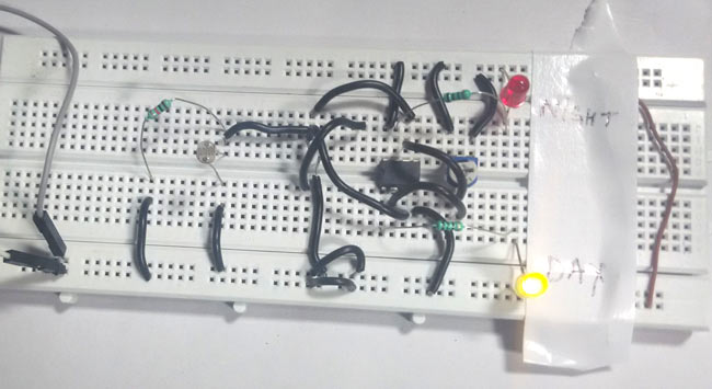
In this project, we are going to make a day and night indicator (or dark and light indicator) which will indicate if there is a dark or light in the surroundings. Some applications of this circuit, are street light controlling, home/office light controlling, day and night indicators, etc.
Components Required
- IC LM358 -1
- 150 Ohm Resistor -2
- 10 K POT -2
- LDR -1
- Bread board -1
- 9 Volt Battery
- Battery Connector -1
- LED -2
IC LM358
LM358 is a Dual Low Noise Operational Amplifier which have two Op Amp in a single chip. This is a general purpose op amp which can be configured in many modes like comparator, summer, integrator, amplifier, differentiator, inverting mode, non- inverting mode and many more.
Circuit Diagram and Working Explanation
In this circuit we have used two LM358 Dual Comparator ICs for comparing voltages coming from variable resistor and LDR. Comparator U1:B is configured as non-inverting mode and 10 K potentiometer is connected at its inverting terminal and Comparator U2:A is configured as inverting mode and same potentiometer is connected at its non-inverting terminal. An LDR is used for detecting light or darkness with respect to ground through a 10K variable resistor. And the midpoint of LDR and resistor is directly connected to inverting terminal of U1:A and non-inverting terminal of U1: B comparator. A red led is connected at output pin of comparator U1: B for indicating Night and a yellow LED is connected at output pin of comparator for indicating Day. And a 9 volt battery is used for powering the circuit. Rest of connections are shown in the above dark and light indicator circuit diagram.
In this circuit we have set reference voltages for both comparators by using potentiometer we can say this sensitivity of the circuit. Both comparators are configured in opposite mode. Means at a time only single LED will glowing. In non-inverting mode when we apply positive voltage greater then reference voltage to its non-inverting pin it gives a positive output else 0 volt. And in inverting mode when we apply same voltage at its inverting pin it will give a 0 volts at its output pin else gives positive voltage. Means both configurations give opposite output.
Main component of this dark circuit is LDR which detect day and light. LDR is a light dependent resistor which changes his resistance according to the light. When light falls on the LDR surface, it reduces its resistance and when dark resistance of LDR become Maximum. During the daytime there are enough light so when this light falls on LDR it reduces its resistance and due to this a potential difference generated at comparators respected pin. Now both comparators compare this input voltage with reference voltage, if this input voltage is greater than reference voltage then day LED will glow otherwise night LED will Glow.
Comments
Adjust the variable resistor
Adjust the variable resistor RV2 properly.
Just interchange inverting
Just interchange inverting and noninverting inputs in op-am
Sir can I ask for a picture
Sir can I ask for a picture of this project done in a PCB board?
You can do it yourself, there
You can do it yourself, there are so many softwares available for Schematic to PCB layout conversion like Easy EDA, Fritzing etc. We have made tutorial for using Easy EDA for PCB conversion Design Your Circuits Online for Free with EasyEDA
Yes it will, but check the
Yes it will, but check the datasheet of 741 for pinouts.
Hello sir,
Hello sir,
I must firstly appreciate this post. I wanna ask if its possible to use a 12Volts DC supply to this circuit. If yes, do I need to change any components? Thank you.


why you use particular value 10k pot