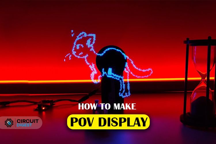
Persistence of Vision is a fundamental principle that allows our eyes to perceive continuous motion from separate images, a concept crucial to the illusion of motion in cinema. When I was a kid, I was always fascinated with it. So, in this project, we are going to use this fascinating optical phenomenon to create a cool-looking POV Display. You must have seen a lot of such projects on the web, but most of them are limited to very low resolution and just display some texts and geometries. We plan to create a POV display that is not limited to just texts or simple shapes. Ours will be able to display images and animations with a resolution of 128 pixels. We have settled with this resolution because it's the sweet spot where we can get decent image quality and it would be easier to build.
We settled on the ESP32 module as the brain of this display, because it is cheap, easy to get and powerful enough to run the display. The display will have two rotating arms, each outfitted with 64 LEDs, to create a total resolution of 128 pixels. The display will rotate at a constant speed, with the LEDs flashing in meticulously orchestrated patterns, controlled by the ESP32 microcontroller. This synchronization allows the display to generate images or text that appear to hover in mid-air, producing a smooth, continuous visual experience. Those who follow us regularly will also know that we built a neopixel POV display earlier, this is an improved version of that project.
The complete project was made possible by our sponsor Viasion Technology, who are also the manufacturers of the PCBs used in this project. We will discuss more about them later in this article.
Features of our POV Display
- 128 Pixel resolution.
- Frame rate of 20 FPS.
- Easy to build.
- Easy to control.
- ESP32 based.
- Fully open source.
- Companion web app to easily convert images.
Components Required to Build the POV Display
The components required to build a POV Display are listed below. The exact value of each component can be found in the schematics or the BOM.
- ESP32 WROOM Module – x1
- 74HC595D shift register – x16
- CH340K USB - UART controller – x1
- TP4056 Li-ion charger IC – x1
- AMS1117 3.3v LDO – x1
- AO3401 P - MOSFET – x1
- 2N7002DW dual N - MOSFET – x1
- Hall effect sensors – x2
- SS34 Diode – x1
- Type C USB Connector 16Pin – x1
- SMD LED Blue 0603 - x128
- 775 Motor – x1
- DC Motor Speed controller – x1
- SMD resistors and capacitors
- SMD LEDs
- SMD Tactile switches
- SDM Slide Switch
- Connectors
- Custom PCB
- 3D printed part and mounting screws.
- Other tools and consumables.
POV Display using ESP32 - Circuit Diagram
The complete circuit diagram for the POV Display is shown below. It can also be downloaded in PDF format from the link given at the end.
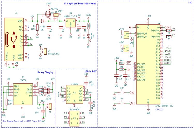
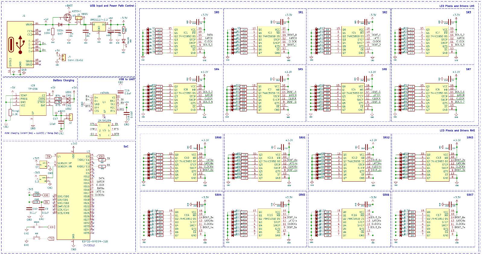
Let’s discuss the Schematics section by section for better understanding. A type C USB port is used for both charging as well as programming purposes. The power from the USB port is connected to a power path controller circuit built around a P-Channel MOSFET U7 and a diode D67. The connector J4 can be used to provide external 5V. The same port can be used to connect a wireless charger module, in case we want to operate it continuously without charging. For voltage regulation, we have used the popular AMS1117 3.3V LDO, which is capable of providing up to 1A of current with an approximate dropout voltage of 1.1V at full load. The connector J3 is used to connect an external switch for turning on and off the entire circuit. For charging the internal battery we are using a TP4056 charge controller which can charge the battery with a maximum charge current of 1A. Now if we look at the programming circuit it is built around the CH340K chip from WCH. For auto reset, we have utilized a dual MOSFET 2N7002DW. Now the brain of the whole circuit is an ESP32-WROOM module. We have chosen this SoC because it is cheap, easily available and powerful enough to drive the display with an adequate frame rate. We have connected the pixels as two sections or hands. Each hand has 64 pixels or LEDs. So, in total, we have a 128-pixel resolution. We have also used two hall effect sensors for RPM measurement and position sensing. In the PCB we have added an SMD footprint for it, but later decided to use a normal A3144 sensor in a TO-92 package since they are easier to procure and easy to mount with the current holder design.
In the next section, we have the LEDs and their drivers. We have used 74HC595D shift registers to drive the LEDs. Since a single s74HC595 can drive up to 8 LEDs, we have used a total of 16 such chips to drive the entire 128 LEDs. We have used a 1KOhms resistor for current limiting, but you can change this value depending on the brightness you need. Since we have two hands, we only need half of a revolution to draw an entire frame or image. The one hand will draw half of the image and the other hand will draw the other half of the image. By doing this we were able to double the frame rate. The display can provide an approximate frame rate of 20FPS.
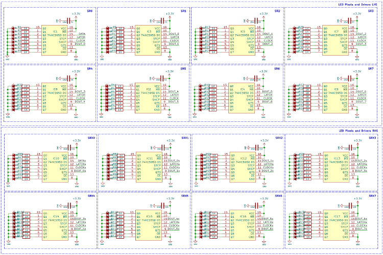
Each pixel will be controlled through these daisy-chained shift registers.
PCB for POV Display
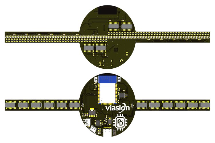
For this project, we have decided to make a custom PCB using KiCad. This will ensure that the final product is as compact as possible as well as easy to assemble and use. The PCB has a dimension of approximately 210mm x 60mm. Here are the top and bottom layers of the PCB.
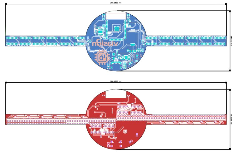
And here is the 3D view of the PCB.
Here is the fully assembled PCB.

Vasion Technology - PCB Manufacturers
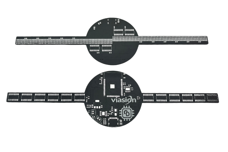
As mentioned earlier the PCB used in this project was fabricated using Viasion Technology, who is an expert in PCB Fabrication and PCB Assembly in China. They have supplied high-quality PCBs to more than 1000 customers worldwide since 2007. Their factory is UL, ISO9001:2016 and ISO13485:2016 certified and is one of the most trusted PCB manufacturers in China for low and medium-volume production.
You can also download the Gerber file for POV display PCB, and contact Viasion Technology to get your PCBs fabricated just like we did. Their packaging and delivery of boards were highly satisfactory and you can also checkout the quality of their PCB boards below.
3D Printed Parts for POV Display
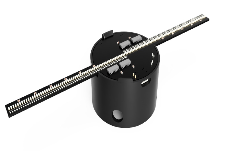
We have designed a cool-looking 3D-printed POV Display using Fusion360. The files for all the 3D printed parts can be downloaded from GitHub link provided at the end of the article along with the Arduino sketch and bitmap file. Learn more about 3D printing and how to get started with it by following the link. Here is the PCB holder with the PCB
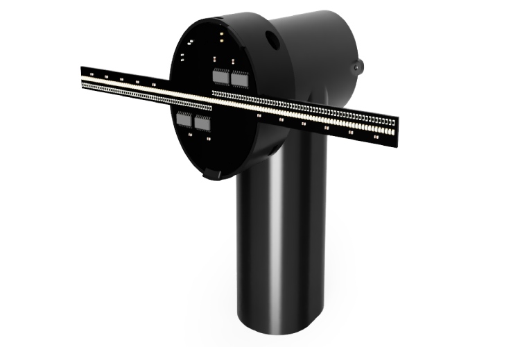
And here is the 3D view of POV display along with the mounting stand. All the models that you see here was created using fusion360.
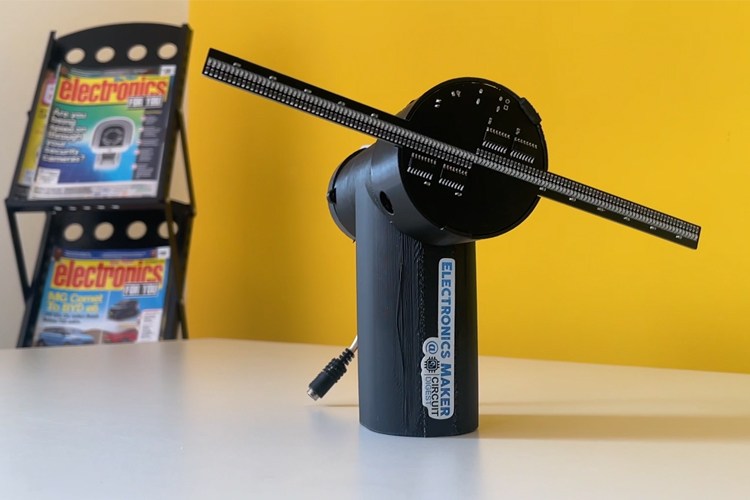
And here is the fully assembled POV LED Display.
How Does the Persistence of Vision Display Work?
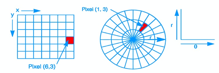
Now let's look at how the POV display works. If you look at the image below you can see that we have divided a circle into 32 equal parts. This indicates a row of pixels. So, if we divide it like this to complete an image, we must draw 32 lines of pixels on every rotation. While displaying each of these lines we must on or off each pixel depending on the pixel data.

In our display, we are dividing each image into 360 pieces radially. This means we must draw 360 lines, that are 1 degree apart, on each rotation to draw an image. In each line, there will be 64 pixels or LEDs (in total 128 LEDs from both arms.) that we should manipulate according to the pixel data. The problem with displaying a normal image is that they use a Cartesian coordinate system. But in order to display an image on a rotating POV display we must need the image with polar coordinates. In a Cartesian coordinate system, The pixels are square, and position is specified by horizontal distance (x) and vertical distance (y). Polar coordinates, on the other hand, are based on a circular grid. The pixels look like wedges or keystones, and position is specified by radius (r) and angle-from-horizontal (θ). Thus, pixels are not uniform: as the distance from the origin increases, the pixels increase in area and change in shape.
To get pixel data from an image we must use some trigonometric calculations and some interpolation. However, doing this for every pixel of every image will take a lot of time and will slowly increase the pixel response time. In order to avoid this and get very minimal pixel repose time and thus maximum refresh rate we will use precomputed value to process the image, which will be explained in the coding section. With our present setup, drawing one frame or an image, with 128-pixel resolution and 360 segments will take around 50ms, thus giving an effective frame rate of 20fps.
The next challenge was to optimize how we store the image. Because, even with normal image arrays that were converted using traditional tools, each pixel will take 1 byte of space. That is, a 128x128 image will need 16384 bytes or 16.384 Kilobytes of space. But with this, we will be limited with the number of images we can store within the code space. To overcome this as well as to get better optimization we have used a new approach. Each row of image pixels will be stored in 16 bytes. Each of these bytes will contain data of 8 pixels as one or zero, i.e. black or white. This data is then will be decoded using a simple function to get the actual pixel data. By using this method one 128x128 pixel image will only need 2048 (128x16) bytes of 2.048 kilobytes of space. Using this method, we were able to reduce the size of an image by 8 times. To convert the image into such a format we have also created a web app. You can access this tool using the following link to convert your images. More details about how to do so are given in the below section. POV Display Image Converter
How to Convert Image to Code for POV display?
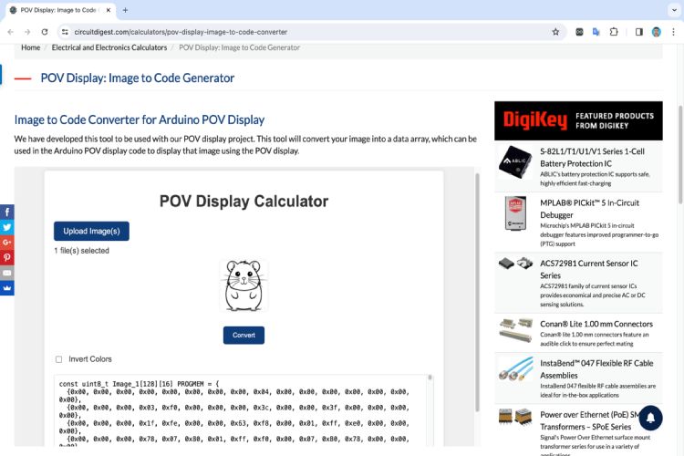
To convert the image, first, make sure your images have a resolution of 128x128 pixels and are in black and white format. Grayscale may not be processed properly. You can convert as many images as you like. To do so open our image converter tool. Once the images are selected click on convert. It will create the corresponding arrays. If you select multiple images the output will have the same number of arrays with the naming like Image_1, Image_2, Image _3 etc… You can copy and paste this array into your code to use them. There will be a check box for inverting colour if you want to. To do so, check the check box and click on the convert button again. It will create new arrays for you to copy.
Arduino Code for POV Display
Now let’s look at the POV display Arduino Code. As usual, we have included all the necessary libraries to the code using the include function, with this code the only third-party library that needed was the MultiShiftRegister that is used to control the 74HC595 shift registers. You can also see that we have also included two header files. The first header file Images.h contains all the images, stored as an optimised data arrays. The Precompute.h header file contains the lookup data, that is used to compute the pixel data using polar coordinates. You can download all these necessary files from the GitHub repo linked at the bottom of this article.
After including the libraries and the necessary header files, we have defined all the necessary global variables. We have also created two shift register instances for each arm. We will use these instances to control the LEDs in each arm separately.
#include <Arduino.h>
#include <MultiShiftRegister.h>
#include "Images.h"
#include "Precompute.h"

// Pin Definitions
#define latchPin 14
#define clockPin 15
#define dataPin 13
#define latchPinx 17
#define clockPinx 18
#define dataPinx 16
#define HALL_SENSOR1_PIN 36
#define HALL_SENSOR2_PIN 39

// Global Variables
volatile unsigned long lastHallTrigger = 0;
volatile float rotationTime = 0;  // Time for one rotation in milliseconds
int hallSensor1State = 0;
int hallSensor2State = 0;
bool halfFrame = false;
int numberOfRegisters = 8;
int offset = 270;
int repeatvalue = 1;
int hys = 3000;
int frame = 0;
int repeat = 0;
int anim = 0;
int frameHoldTime = 1;     // Number of loops to hold each frame
int frameHoldCounter = 0;  // Counter to track loops for current frame

//Shift register Driver instances for both hands
MultiShiftRegister msr(numberOfRegisters, latchPin, clockPin, dataPin);
MultiShiftRegister msrx(numberOfRegisters, latchPinx, clockPinx, dataPinx);
Next we have the getValueFromAngle function which takes 3 parameters, that includes, the name of a 2D array, angle and radius, and returns the pixel data. The function gets the angle and process it using the offset value to get the corrected angle. Then this corrected angle is used with the radius and values from the precomputedCos and PrecomputedSin arrays to calculate the X and Y data for the corresponding pixel. Then it extracts the value of this pixel and returns it.
//Function to calculate polar co-ordintes, and get corresponding data from the arrays.
int getValueFromAngle(const uint8_t arrayName[][16], int angle, int radius) {
  // Adjust the angle by subtracting offset to rotate counter-clockwise
  int adjustedAngle = angle - offset;
  if (adjustedAngle < 0) adjustedAngle += 360;  // Ensure the angle stays within 0-359 degrees

  // Invert the targetX calculation to flip the image horizontally
  int targetX = 127 - precomputedCos[radius][adjustedAngle];  // Flipping targetX
  int targetY = precomputedSin[radius][adjustedAngle];
  if (targetX >= 0 && targetX < 128 && targetY >= 0 && targetY < 128) {
    int byteIndex = targetX / 8;
    int bitIndex = 7 - (targetX % 8);
    return (arrayName[targetY][byteIndex] >> bitIndex) & 1;  // Extract the bit value and return it
  } else {
    return -1;  // Out of bounds
  }
}
Then we have two interrupt routines for both hall sensors. The first routine is used for both position sensing as well as for measuring the rotation speed. The second routine is used for just the position sensing. We have used two sensors for this because we only need a half rotation to draw an image. So sensing the position every half rotation is critical for display synching.
//Hall sensor 1 interrupt routine
void ISR_HallSensor1() {
  unsigned long currentTime = micros();
  // Check if HYS ms have passed since the last trigger
  if (currentTime - lastHallTrigger >= hys) {
    rotationTime = (currentTime - lastHallTrigger) / 1000.0;
    lastHallTrigger = currentTime;
    hallSensor1State = 1;
    halfFrame = true;
  }
}

//Hall sensor 2 interrupt routine
void ISR_HallSensor2() {
  unsigned long currentTime = micros();
  // Check if HYS ms have passed since the last trigger
  if (currentTime - lastHallTrigger >= hys) {
    lastHallTrigger = currentTime;
    hallSensor2State = 1;
    halfFrame = false;
  }
}
Later we have the DisplayFrame function. This function handles the image fetching and image drawing. It draws the images line by line the first arm used to draw the first half while the second arm is used to draw the opposite half of the image at the same time. It also synchronises the frame draw time using the RPM data from the interrupt routine.
//Function to calculate RPM and display each frame accordingly
void DisplayFrame(const uint8_t ImageName[][16]) {
  float timePerSegment = rotationTime / 360.0;  // Assuming 180 segments per half rotation

  for (int i = 0; i < 180; i++) {
    unsigned long segmentStartTime = micros();

    for (int j = 0; j < 64; j++) {
      // First arm (msr) displays the first half of the frame
      if (getValueFromAngle(ImageName, i + (halfFrame ? 0 : 180), j)) {
        msr.set(j);
      } else {
        msr.clear(j);
      }

      // Second arm (msrx) displays the second half of the frame
      if (getValueFromAngle(ImageName, i + (halfFrame ? 180 : 0), j)) {
        msrx.set(j);
      } else {
        msrx.clear(j);
      }
    }

    msr.shift();
    msrx.shift();

    while (micros() - segmentStartTime < timePerSegment * 1000)
      ;
  }
}
In the setup function, we have initialized all the required pins as inputs and outputs. Then we have attached the two interrupts to the corresponding pins with rising edge. Then we have turned off all the pixels before drawing anything.
void setup() {
  // Initialize pins
  pinMode(latchPin, OUTPUT);
  pinMode(clockPin, OUTPUT);
  pinMode(dataPin, OUTPUT);
  pinMode(latchPinx, OUTPUT);
  pinMode(clockPinx, OUTPUT);
  pinMode(dataPinx, OUTPUT);
  pinMode(HALL_SENSOR1_PIN, INPUT);
  pinMode(HALL_SENSOR2_PIN, INPUT);

  attachInterrupt(digitalPinToInterrupt(HALL_SENSOR1_PIN), ISR_HallSensor1, RISING);
  attachInterrupt(digitalPinToInterrupt(HALL_SENSOR2_PIN), ISR_HallSensor2, RISING);
  for (int i = 0; i < 64; i++) {
    msr.clear(i);
    msrx.clear(i);
  }
  msr.shift();
  msrx.shift();
  Serial.begin(115200);
}
The loop function draws all the animations and images one by one. The variable anim is used to loop through each image and animation. The variable frameHoldeTime controls the animation speed. Of you set the this to two, the animation will be played in half the speed and if you put four it would be played in ¼ speed , and so on. Another variable repeatvalue determines how may time you need to play the animation. One means it will only be played once before playing the next one, and if it is 2 it will be played twice, and so on. Each of this variables should bet in the previous image or animation.
void loop() {
  if (hallSensor1State || hallSensor2State) {
    if (anim == 0) {
      DisplayFrame(CDArrays[frame]);
      // Increment the counter
      frameHoldCounter++;
      // Check if it's time to move to the next frame
      if (frameHoldCounter >= frameHoldTime) {
        // Reset the counter
        frameHoldCounter = 0;
        // Move to the next frame
        frame++;
        if (frame > 21) {
          frame = 0;
          repeat++;
          if (repeat == 1) {
            repeat = 0;
            anim++;
            frameHoldTime = 1;
            repeatvalue = 1;
          }
        }
      }
    }
    if (anim == 1) {
      DisplayFrame(ImageCD_22);
      // Increment the counter
      frameHoldCounter++;
      // Check if it's time to move to the next frame
      if (frameHoldCounter >= frameHoldTime) {
        // Reset the counter
        frameHoldCounter = 0;
        // Move to the next frame
        frame++;
        if (frame > 50) {
          frame = 0;
          repeat++;
          if (repeat == repeatvalue) {
            repeat = 0;
            anim++;
            frameHoldTime = 2;
            repeatvalue = 1;
          }
        }
      }
    }
    if (anim == 2) {
      DisplayFrame(ViasionArrays[frame]);
      // Increment the counter
      frameHoldCounter++;
      // Check if it's time to move to the next frame
      if (frameHoldCounter >= frameHoldTime) {
        // Reset the counter
        frameHoldCounter = 0;
        // Move to the next frame
        frame++;
        if (frame > 21) {
          frame = 0;
          repeat++;
          if (repeat == repeatvalue) {
            repeat = 0;
            anim++;
            frameHoldTime = 1;
            repeatvalue = 1;
          }
        }
      }
    }
    if (anim == 3) {
      DisplayFrame(Image_Viasion22);
      // Increment the counter
      frameHoldCounter++;
      // Check if it's time to move to the next frame
      if (frameHoldCounter >= frameHoldTime) {
        // Reset the counter
        frameHoldCounter = 0;
        // Move to the next frame
        frame++;
        if (frame > 50) {
          frame = 0;
          repeat++;
          if (repeat == repeatvalue) {
            repeat = 0;
            anim++;
            frameHoldTime = 2;
            repeatvalue = 1;
          }
        }
      }
    }
    if (anim == 4) {
      DisplayFrame(ViasionOTRArrays[frame]);
      // Increment the counter
      frameHoldCounter++;
      // Check if it's time to move to the next frame
      if (frameHoldCounter >= frameHoldTime) {
        // Reset the counter
        frameHoldCounter = 0;
        // Move to the next frame
        frame++;
        if (frame > 11) {
          frame = 0;
          repeat++;
          if (repeat == repeatvalue) {
            repeat = 0;
            anim++;
            frameHoldTime = 1;
            repeatvalue = 10;
          }
        }
      }
    }
    if (anim == 5) {
      DisplayFrame(CatRunArray[frame]);
      // Increment the counter
      frameHoldCounter++;
      // Check if it's time to move to the next frame
      if (frameHoldCounter >= frameHoldTime) {
        // Reset the counter
        frameHoldCounter = 0;
        // Move to the next frame
        frame++;
        if (frame > 9) {
          frame = 0;
          repeat++;
          if (repeat == repeatvalue) {
            repeat = 0;
            anim++;
            frameHoldTime = 2;
            repeatvalue = 2;
          }
        }
      }
    } else if (anim == 6) {
      DisplayFrame(CatArrays[frame]);
      // Increment the counter
      frameHoldCounter++;
      // Check if it's time to move to the next frame
      if (frameHoldCounter >= frameHoldTime) {
        // Reset the counter
        frameHoldCounter = 0;
        // Move to the next frame
        frame++;
        if (frame > 61) {
          frame = 0;
          repeat++;
          if (repeat == repeatvalue) {
            repeat = 0;
            anim++;
            frameHoldTime = 2;
            repeatvalue = 3;
          }
        }
      }
    } else if (anim == 7) {
      DisplayFrame(RunningSFArrays[frame]);
      // Increment the counter
      frameHoldCounter++;
      // Check if it's time to move to the next frame
      if (frameHoldCounter >= frameHoldTime) {
        // Reset the counter
        frameHoldCounter = 0;
        // Move to the next frame
        frame++;
        if (frame > 11) {
          frame = 0;
          repeat++;
          if (repeat == repeatvalue) {
            repeat = 0;
            anim++;
            frameHoldTime = 2;
            repeatvalue = 1;
          }
        }
      }
    } else if (anim == 8) {
      DisplayFrame(Dance1Arrays[frame]);
      // Increment the counter
      frameHoldCounter++;
      // Check if it's time to move to the next frame
      if (frameHoldCounter >= frameHoldTime) {
        // Reset the counter
        frameHoldCounter = 0;
        // Move to the next frame
        frame++;
        if (frame > 93) {
          frame = 0;
          repeat++;
          if (repeat == repeatvalue) {
            repeat = 0;
            anim++;
            frameHoldTime = 1;
            repeatvalue = 4;
          }
        }
      }
    } else if (anim == 9) {
      DisplayFrame(EYEArrays[frame]);  // Increment the counter
      frameHoldCounter++;
      // Check if it's time to move to the next frame
      if (frameHoldCounter >= frameHoldTime) {
        // Reset the counter
        frameHoldCounter = 0;
        // Move to the next frame
        frame++;
        if (frame > 73) {
          frame = 0;
          repeat++;
          if (repeat == repeatvalue) {
            repeat = 0;
            anim++;
            frameHoldTime = 2;
            repeatvalue = 4;
          }
        }
      }
    } else if (anim == 10) {
      DisplayFrame(GlobexArrays[frame]);  // Increment the counter
      frameHoldCounter++;
      // Check if it's time to move to the next frame
      if (frameHoldCounter >= frameHoldTime) {
        // Reset the counter
        frameHoldCounter = 0;
        // Move to the next frame
        frame++;
        if (frame > 14) {
          frame = 0;
          repeat++;
          if (repeat == repeatvalue) {
            repeat = 0;
            anim++;
            frameHoldTime = 20;
            repeatvalue = 1;
          }
        }
      }
    } else if (anim == 11) {
      DisplayFrame(ClockArrays[frame]);  // Increment the counter
      frameHoldCounter++;
      // Check if it's time to move to the next frame
      if (frameHoldCounter >= frameHoldTime) {
        // Reset the counter
        frameHoldCounter = 0;
        // Move to the next frame
        frame++;
        if (frame > 13) {
          frame = 0;
          repeat++;
          if (repeat == repeatvalue) {
            repeat = 0;
            anim = 0;
            frameHoldTime = 2;
            repeatvalue = 1;
          }
        }
      }
    }
    hallSensor1State = 0;
    hallSensor2State = 0;
  }
}
So that’s it with the code. While compiling make sure to select large app with no OTA as the partition format, since the code contains a number of animations and effect, and it requires a bit of code space. Now make your own POV display using all these details and enjoy. You can also check out our other ESP32 projects, if you want to explore more.
Supporting Files
Here is the link to our GitHub repo, where you'll find the source code, schematics, and all other necessary files to build your own POV Display.
/*
* Project Name: POV display
* Project Brief: Firmware for ESP32 POV Display. Display resolution 128 pixels
* Author: Jobit Joseph
* Copyright © Jobit Joseph
* Copyright © Semicon Media Pvt Ltd
* Copyright © Circuitdigest.com
*
* This program is free software: you can redistribute it and/or modify
* it under the terms of the GNU General Public License as published by
* the Free Software Foundation, in version 3.
*
* This program is distributed in the hope that it will be useful,
* but WITHOUT ANY WARRANTY; without even the implied warranty of
* MERCHANTABILITY or FITNESS FOR A PARTICULAR PURPOSE. See the
* GNU General Public License for more details.
*
* You should have received a copy of the GNU General Public License
* along with this program. If not, see <http://www.gnu.org/licenses/>.
*
*/
#include <Arduino.h>
#include <MultiShiftRegister.h>
#include "Images.h"
#include "Precompute.h"
// Pin Definitions
#define latchPin 14
#define clockPin 15
#define dataPin 13
#define latchPinx 17
#define clockPinx 18
#define dataPinx 16
#define HALL_SENSOR1_PIN 36
#define HALL_SENSOR2_PIN 39
// Global Variables
volatile unsigned long lastHallTrigger = 0;
volatile float rotationTime = 0; // Time for one rotation in milliseconds
int hallSensor1State = 0;
int hallSensor2State = 0;
bool halfFrame = false;
int numberOfRegisters = 8;
int offset = 270;
int repeatvalue = 1;
int hys = 3000;
int frame = 0;
int repeat = 0;
int anim = 0;
int frameHoldTime = 1; // Number of loops to hold each frame
int frameHoldCounter = 0; // Counter to track loops for current frame
//Shift register Driver instances for both hands
MultiShiftRegister msr(numberOfRegisters, latchPin, clockPin, dataPin);
MultiShiftRegister msrx(numberOfRegisters, latchPinx, clockPinx, dataPinx);
//Function to calculate polar co-ordintes, and get corresponding data from the arrays.
int getValueFromAngle(const uint8_t arrayName[][16], int angle, int radius) {
// Adjust the angle by subtracting offset to rotate counter-clockwise
int adjustedAngle = angle - offset;
if (adjustedAngle < 0) adjustedAngle += 360; // Ensure the angle stays within 0-359 degrees
// Invert the targetX calculation to flip the image horizontally
int targetX = 127 - precomputedCos[radius][adjustedAngle]; // Flipping targetX
int targetY = precomputedSin[radius][adjustedAngle];
if (targetX >= 0 && targetX < 128 && targetY >= 0 && targetY < 128) {
int byteIndex = targetX / 8;
int bitIndex = 7 - (targetX % 8);
return (arrayName[targetY][byteIndex] >> bitIndex) & 1; // Extract the bit value and return it
} else {
return -1; // Out of bounds
}
}
//Hall sensor 1 interrupt routine
void ISR_HallSensor1() {
unsigned long currentTime = micros();
// Check if HYS ms have passed since the last trigger
if (currentTime - lastHallTrigger >= hys) {
rotationTime = (currentTime - lastHallTrigger) / 1000.0;
lastHallTrigger = currentTime;
hallSensor1State = 1;
halfFrame = true;
}
}
//Hall sensor 2 interrupt routine
void ISR_HallSensor2() {
unsigned long currentTime = micros();
// Check if HYS ms have passed since the last trigger
if (currentTime - lastHallTrigger >= hys) {
lastHallTrigger = currentTime;
hallSensor2State = 1;
halfFrame = false;
}
}
//Function to calculate RPM and display each frame accordingly
void DisplayFrame(const uint8_t ImageName[][16]) {
float timePerSegment = rotationTime / 360.0; // Assuming 180 segments per half rotation
for (int i = 0; i < 180; i++) {
unsigned long segmentStartTime = micros();
for (int j = 0; j < 64; j++) {
// First arm (msr) displays the first half of the frame
if (getValueFromAngle(ImageName, i + (halfFrame ? 0 : 180), j)) {
msr.set(j);
} else {
msr.clear(j);
}
// Second arm (msrx) displays the second half of the frame
if (getValueFromAngle(ImageName, i + (halfFrame ? 180 : 0), j)) {
msrx.set(j);
} else {
msrx.clear(j);
}
}
msr.shift();
msrx.shift();
while (micros() - segmentStartTime < timePerSegment * 1000)
;
}
}
void setup() {
// Initialize pins
pinMode(latchPin, OUTPUT);
pinMode(clockPin, OUTPUT);
pinMode(dataPin, OUTPUT);
pinMode(latchPinx, OUTPUT);
pinMode(clockPinx, OUTPUT);
pinMode(dataPinx, OUTPUT);
pinMode(HALL_SENSOR1_PIN, INPUT);
pinMode(HALL_SENSOR2_PIN, INPUT);
attachInterrupt(digitalPinToInterrupt(HALL_SENSOR1_PIN), ISR_HallSensor1, RISING);
attachInterrupt(digitalPinToInterrupt(HALL_SENSOR2_PIN), ISR_HallSensor2, RISING);
for (int i = 0; i < 64; i++) {
msr.clear(i);
msrx.clear(i);
}
msr.shift();
msrx.shift();
Serial.begin(115200);
}
void loop() {
if (hallSensor1State || hallSensor2State) {
if (anim == 0) {
DisplayFrame(CDArrays[frame]);
// Increment the counter
frameHoldCounter++;
// Check if it's time to move to the next frame
if (frameHoldCounter >= frameHoldTime) {
// Reset the counter
frameHoldCounter = 0;
// Move to the next frame
frame++;
if (frame > 21) {
frame = 0;
repeat++;
if (repeat == 1) {
repeat = 0;
anim++;
frameHoldTime = 1;
repeatvalue = 1;
}
}
}
}
if (anim == 1) {
DisplayFrame(ImageCD_22);
// Increment the counter
frameHoldCounter++;
// Check if it's time to move to the next frame
if (frameHoldCounter >= frameHoldTime) {
// Reset the counter
frameHoldCounter = 0;
// Move to the next frame
frame++;
if (frame > 50) {
frame = 0;
repeat++;
if (repeat == repeatvalue) {
repeat = 0;
anim++;
frameHoldTime = 2;
repeatvalue = 1;
}
}
}
}
if (anim == 2) {
DisplayFrame(ViasionArrays[frame]);
// Increment the counter
frameHoldCounter++;
// Check if it's time to move to the next frame
if (frameHoldCounter >= frameHoldTime) {
// Reset the counter
frameHoldCounter = 0;
// Move to the next frame
frame++;
if (frame > 21) {
frame = 0;
repeat++;
if (repeat == repeatvalue) {
repeat = 0;
anim++;
frameHoldTime = 1;
repeatvalue = 1;
}
}
}
}
if (anim == 3) {
DisplayFrame(Image_Viasion22);
// Increment the counter
frameHoldCounter++;
// Check if it's time to move to the next frame
if (frameHoldCounter >= frameHoldTime) {
// Reset the counter
frameHoldCounter = 0;
// Move to the next frame
frame++;
if (frame > 50) {
frame = 0;
repeat++;
if (repeat == repeatvalue) {
repeat = 0;
anim++;
frameHoldTime = 2;
repeatvalue = 1;
}
}
}
}
if (anim == 4) {
DisplayFrame(ViasionOTRArrays[frame]);
// Increment the counter
frameHoldCounter++;
// Check if it's time to move to the next frame
if (frameHoldCounter >= frameHoldTime) {
// Reset the counter
frameHoldCounter = 0;
// Move to the next frame
frame++;
if (frame > 11) {
frame = 0;
repeat++;
if (repeat == repeatvalue) {
repeat = 0;
anim++;
frameHoldTime = 1;
repeatvalue = 10;
}
}
}
}
if (anim == 5) {
DisplayFrame(CatRunArray[frame]);
// Increment the counter
frameHoldCounter++;
// Check if it's time to move to the next frame
if (frameHoldCounter >= frameHoldTime) {
// Reset the counter
frameHoldCounter = 0;
// Move to the next frame
frame++;
if (frame > 9) {
frame = 0;
repeat++;
if (repeat == repeatvalue) {
repeat = 0;
anim++;
frameHoldTime = 2;
repeatvalue = 2;
}
}
}
} else if (anim == 6) {
DisplayFrame(CatArrays[frame]);
// Increment the counter
frameHoldCounter++;
// Check if it's time to move to the next frame
if (frameHoldCounter >= frameHoldTime) {
// Reset the counter
frameHoldCounter = 0;
// Move to the next frame
frame++;
if (frame > 61) {
frame = 0;
repeat++;
if (repeat == repeatvalue) {
repeat = 0;
anim++;
frameHoldTime = 2;
repeatvalue = 3;
}
}
}
} else if (anim == 7) {
DisplayFrame(RunningSFArrays[frame]);
// Increment the counter
frameHoldCounter++;
// Check if it's time to move to the next frame
if (frameHoldCounter >= frameHoldTime) {
// Reset the counter
frameHoldCounter = 0;
// Move to the next frame
frame++;
if (frame > 11) {
frame = 0;
repeat++;
if (repeat == repeatvalue) {
repeat = 0;
anim++;
frameHoldTime = 2;
repeatvalue = 1;
}
}
}
} else if (anim == 8) {
DisplayFrame(Dance1Arrays[frame]);
// Increment the counter
frameHoldCounter++;
// Check if it's time to move to the next frame
if (frameHoldCounter >= frameHoldTime) {
// Reset the counter
frameHoldCounter = 0;
// Move to the next frame
frame++;
if (frame > 93) {
frame = 0;
repeat++;
if (repeat == repeatvalue) {
repeat = 0;
anim++;
frameHoldTime = 1;
repeatvalue = 4;
}
}
}
} else if (anim == 9) {
DisplayFrame(EYEArrays[frame]); // Increment the counter
frameHoldCounter++;
// Check if it's time to move to the next frame
if (frameHoldCounter >= frameHoldTime) {
// Reset the counter
frameHoldCounter = 0;
// Move to the next frame
frame++;
if (frame > 73) {
frame = 0;
repeat++;
if (repeat == repeatvalue) {
repeat = 0;
anim++;
frameHoldTime = 2;
repeatvalue = 4;
}
}
}
} else if (anim == 10) {
DisplayFrame(GlobexArrays[frame]); // Increment the counter
frameHoldCounter++;
// Check if it's time to move to the next frame
if (frameHoldCounter >= frameHoldTime) {
// Reset the counter
frameHoldCounter = 0;
// Move to the next frame
frame++;
if (frame > 14) {
frame = 0;
repeat++;
if (repeat == repeatvalue) {
repeat = 0;
anim++;
frameHoldTime = 20;
repeatvalue = 1;
}
}
}
} else if (anim == 11) {
DisplayFrame(ClockArrays[frame]); // Increment the counter
frameHoldCounter++;
// Check if it's time to move to the next frame
if (frameHoldCounter >= frameHoldTime) {
// Reset the counter
frameHoldCounter = 0;
// Move to the next frame
frame++;
if (frame > 13) {
frame = 0;
repeat++;
if (repeat == repeatvalue) {
repeat = 0;
anim = 0;
frameHoldTime = 2;
repeatvalue = 1;
}
}
}
}
hallSensor1State = 0;
hallSensor2State = 0;
}
}
Comments
The image converter is hard…
The image converter is hard coded for 128x128 images. So will have to make a new script or something to converter the low resolution image.



This is the best POV display I have come across. The best with animation. I wish to build a similar one but with lesser leds,say 30 per arm. How to modify the code received from the image converter tool ?