

In this project, we have used the popular ESP32-CAM module to build an Image recognition system that can identify various vegetables. We have used the Edge Impulse platform to train our model and deployed it on the ESP32cam module, the results of the model are displayed on the OLED screen as output. In this tutorial we will understand the basics of edge computing and how to use edge impulse with ESP32 CAM to train and deploy your own object detection model using AI to identify any object of your choice. We have also built many similar AI projects previously here at circuitdigest, you can also check them out if you wish to explore more.
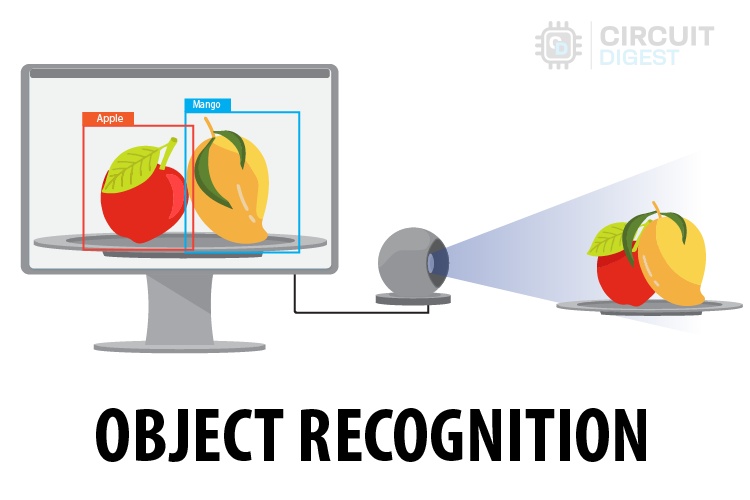
The above image shows a quick working demonstration of our project, you can notice how the ESP32 cam module detects the object in front of it and displays it on the OLED screen below.
What is AI on Edge?
Edge computing or AI on Edge is a technology that allows artificial intelligence algorithms to run on small, low-power devices like microcontrollers or microprocessors. This approach aims to reduce costs and enhance system performance by processing data locally, rather than sending it to distant servers. While cloud computing has been popular due to its lower initial setup and maintenance costs, advancements in technology now make edge computing a viable and efficient option. In essence, edge computing brings powerful processing capabilities directly to where the data is generated, making systems faster and more efficient.
What is Object Recognition?
In technical terms “Object recognition is a technology in the field of computer vision and artificial intelligence that involves identifying and labeling objects within an image or a video. This process enables machines to interpret and understand the visual world much like humans do.” Also do know that the terms like object detection or object recognition or image recognition are often used interchangeably because they mean the same. In this esp32 cam object detection project we are going to show you how to recognize the type of vegetable in front of the ESP32 cam modules camera, namely if its an onion, potato or tomato.
Let's understand the processes required for a system to recognize objects in an image.
- Data Acquisition: The process starts with data acquisition. Collect multiple images of the object you want the system to recognize.
- Preprocessing the Acquired Data: The collected images are then preprocessed to support the next steps. This usually involves noise reduction, contrast enhancement, and scaling.
- Feature Extraction: Key features of the image, such as texture, shape, color, and edges, are extracted for use in training the system.
- Training the Model: Machine learning models, like Convolutional Neural Networks (CNNs), are trained on a large dataset of labeled images. The model learns to associate extracted features with specific objects.
- Testing the Model: After training, the model is ready for testing and deployment. The model recognizes individual objects and compares them with the extracted features from the training dataset. It then plots the location and names the detected objects. To improve accuracy, train the model with a larger dataset.
- Deployment of the Model: Based on system constraints, the trained model's format is converted and run on the system. Here, it's expected to have more accuracy in the detection; otherwise, we need to concentrate more on data acquisition and training the model.
Now, let’s look at the components required to do our experiment.
Components Required for ESP32 CAM Object Detection Project
As testing hardware, we selected the ESP32-CAM, which is a low-cost microcontroller with a built-in camera. Since we selected the ESP32-CAM, we need an additional programmer, which is a USB to Serial Converter. Additionally, I selected some vegetables for performing object recognition. Initially, it looks simple, but it is tougher than I thought. The rest of the story will be discussed below. Now, let's look at the list of components we need:
- ESP32-CAM x1
- USB to Serial Converter x1
- Breadboard x1
- 0.96” OLED Display x1 (optional)
- Jumper wires (required quantity)
- Some vegetables - I am using tomato, potato, and onion, 3 each
In the software part, there are two main things we are going to look at: Edge Impulse and Arduino IDE. Edge Impulse is where I am going to use it for all ML purposes, and Arduino IDE is for programming and debugging the ESP32-CAM. As a list, you can see below:
Circuit Diagram for ESP32CAM Image Recogniton
The circuit diagram need for this object detection project is very simple as there are not many components here. The OLED is optional, so it depends on your preference. I used the OLED so that easy to demonstrate the working of the project. If you are looking to keep it simple, you can use the serial monitor to view the results of the object detection.

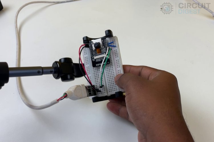
Follow the above circuit diagram and make the connections accordingly. We have also shown how the FTDI programmer (red board) is connected to the ESP32 for programming. If you are completely new to using ESP32CAM module, you can visit our article covering "How to Program the ESP32-CAM?", which will help you understand everything about programming the ESP32-CAM.
Introduction to Edge Impulse
Edge Impulse is a revolutionary platform designed for developers to seamlessly create, optimize, and deploy machine learning models directly onto edge devices. By harnessing its intuitive interface and powerful tools, developers can efficiently collect data, train models, and integrate them into real-world applications-all while benefiting from Edge Impulse's robust support for various hardware platforms and sensors.

This enables rapid innovation in the field of edge computing, facilitating smarter and more responsive devices across industries such as IoT, robotics, and mobile technology. To learn more about Edge Impulse and explore its powerful features, visit their official website. You can also check out our Edge Impulse Projects if you need more tutorials on how to build using Edge Impulse.
ESP32 CAM Edge Impulse
Hope you understand something about Edge Impulse; that's why we are going to use Edge Impulse to create an Object Detection System using the cheapest camera module out there in the market, which is ESP32-CAM. So, to make it a simple tutorial on this concept, we selected the concept of vegetable classification. We are going to classify three vegetables, namely Potato, Tomato, and Onion. You can use whatever objects to make an object recognition.
What we are going to do is:
- Collecting the dataset directly using ESP32-CAM with its built-in camera.
- Utilizing Edge Impulse to build a machine-learning model that is compatible with ESP32-CAM.
- Verifying and testing the machine learning model in real time.
Remember that we will not be covering all the features of Edge Impulse. There is already well-written documentation by Edge Impulse. If you wish to learn more, kindly visit their official website, which is Edge Impulse Documentation.
How to use ESP32 CAM for Object Recognition
These procedures can be split into three main parts: Data Acquisition, Building the ML Model using Edge Impulse, and Testing the Prototype.
Data Acquisition:
Data acquisition can be done in three general ways. You can follow whichever process you feel comfortable with.
Check List to Remember:
- Need to collect at least 50 images of each object that we are looking to classify. More images mean more accuracy; that’s the universal rule.
- The object can have any background, but a plain, empty background is preferred.
- Higher resolution takes more time for training, so select an optimum resolution. In our case, 256x256px is sufficient.
Our concentration in this article is going to be on vegetables, especially tomatoes, potatoes, and onions.
Option 1: Searching for DataSets online
The first and easiest way for data acquisition is finding the dataset directly on the internet. There are sites like Kaggle, Google Dataset Search, OpenML, etc. You can search there directly. In our case, we are going to classify vegetables, so we need images of tomatoes, potatoes, and onions.
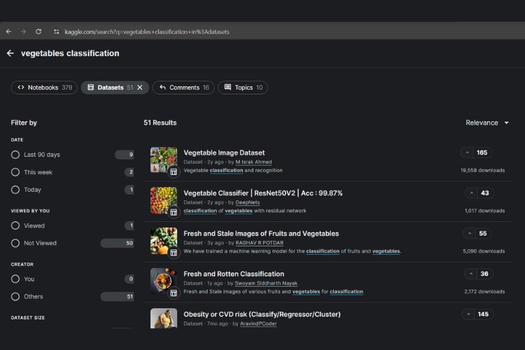
As discussed, search for the dataset on any of the websites and find the dataset suitable for your needs. Just remember to adhere to the checklist while collecting the dataset. In the above image, you can see the search results of the data I searched for on Kaggle. It may take some time to choose the right one. However, I am not going to collect data using this method due to some factors that we will discuss soon.
Option 2: Collecting Images one by one online
The next step is straightforward: searching for images on Google and downloading them one by one. This is a more time-consuming process. Make sure the downloaded images have no watermark. Otherwise, everything is fine; once again, verify the checklist. Next, Let's Move to the Next Possible Way Which I Am Going to Prefer:
Option 3: Capturing Our Own Images
Now comes the interesting part, creating our own datasets using our own collected data. Here you can have multiple ways, like capturing on your mobile, using Edge Impulse itself for capturing via mobile or webcam, or using ESP32-CAM’s camera. It's easy to use a mobile phone or webcam to record images using Edge Impulse, so I am not going to explain that. Instead, I will be focusing on image acquisition using ESP32-CAM itself. This is possible using the library EloquentEsp32cam, which has an example code that can make ESP32-CAM work as a web server with a basic interface necessary to click photos for creating datasets.
Step 1: Installing the Library
We need to install the EloquentEsp32cam Library, which you can find in the library manager.
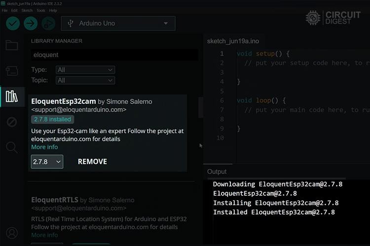
Above, you can see the installation of the Eloquent ESP32-CAM Library.
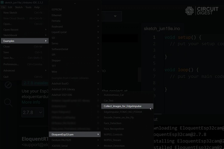
Step 2: Opening the Example Program and Doing Necessary Modifications
Open the example program which is located in Examples -> EloquentEsp32cam -> Collect_Images_for_EdgeImpulse, as shown in the image below.
Next, in that program, we need to enter our Wi-Fi hotspot credentials.
#define WIFI_SSID "SSID"
#define WIFI_PASS "PASSWORD"
#define HOSTNAME "esp32cam"
You can see the above lines at the start of the program. Kindly enter your Wi-Fi hotspot name in “SSID” and password in "PASSWORD". Remember that the ESP32 is compatible only with the 2.4 GHz network. Now all is set and the code is ready for uploading. If you don’t know about uploading, kindly see the following article which covers how to program the ESP32-CAM.
Step 3: Accessing the Web Server of ESP32-CAM and Capturing the Data
Finding the IP address is easy; you can use the serial monitor to identify the IP address. When the system boots successfully, it will print the local IP address serially via 115200 BaudRate. By copying and pasting this into any browser on any device connected to the same network, you will access the web server hosted by the ESP32-CAM.
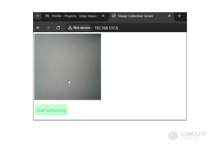
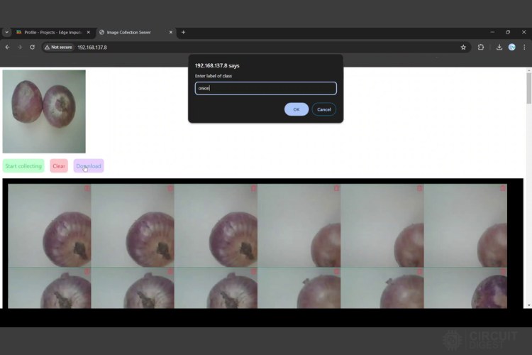
Once after a successful connection, you can see a window similar to the one above. The UI is straightforward: press "START COLLECTING" to capture footage. While starting to capture, you will see two new additional buttons, "Clear" and "Download". Once you have enough data, click the "Download" button and provide the label name. A zip folder will be downloaded successfully.
Remember to ensure a clear view and good lighting for the object that you are going to capture. An empty area with a single-colored background, especially white, is highly recommended.
Similarly, follow this process for tomatoes and potatoes. Next, let's move to the Edge Impulse part.
Edge Impulse in Action
Finally, we come to the Edge Impulse side of our project. Here, the process is simple and easy to follow. The overall process will be as follows: Signing up for Edge Impulse, Data Acquisition in Edge Impulse, Creating Impulse, Generating Features, Training the ML Model, and Deploying the Model in ESP32-CAM. So, let's get to work!
Step 1: Signing up for Edge Impulse
It's a simple process. Still, I have added the screenshots for your reference which you can see below.
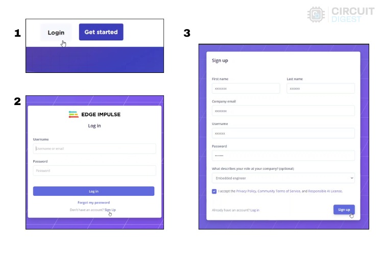
First, head to the Edge Impulse site, go to the "Sign in" option, and then select the "Sign up" option to reach the sign-up page. Once you finish signing up, log in to your account.
Step 2: Creating a New Project in Edge Impulse
After signing in to Edge Impulse, click on "Create new project." Then, enter the title of the project; I am going with "Vegetable Identification" Next, leave the rest of the settings as default, and click "Create new project"
Now, you will be able to see the main dashboard of your project.
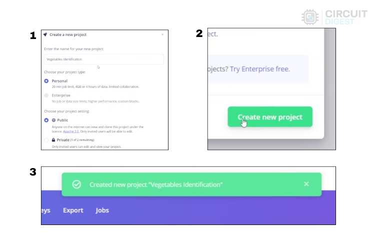
The above image clearly shows the steps used while creating a new project.
Step 3: Data Acquisition in Edge Impulse
On the left, you can find the "Data Acquisition" option. Clicking on that will direct you to the page where you add and label data. Here, you can also see various perspectives for the dataset. You can view individual data in the training and testing sets and more.
Here, you can see the "Collect data" option to collect the data using a webcam, your mobile device, or even using any of the supported development boards.
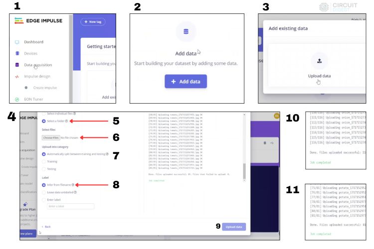
Follow the above steps to add each folder to your dataset collection. That's it; next, we are going to label our data.
At the top, you can see the menu "Labeling Queue." Select that, and you will be directed to the window where you can start labeling the images you have added. This is actually a bit time-consuming. You need to draw a bounding box one by one for all the data you have collected.
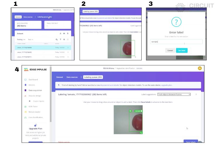
The above image shows the steps for labeling the objects. While labeling, try to make a square boundary as the data will be processed in 96 x 96 px. So, mostly try to make it square to get the maximum accuracy out of the system.
In the labeling window, you can see an option like "Label Suggestions." It is very useful if you have high-quality images or continuous images. If it is in "Track objects between frames," the object you drew a bounding box around once is then tracked in the upcoming frames, thus reducing the work time. Next, you can use "Classify using YOLOv5" to recognize some of the common objects automatically by the system. This way, it labels and draws the bounding box itself.
Therefore, we have finished our tasks in the area of Data Acquisition. Next, let's look at creating the impulse.
Step 4: Creating Impulse
Here we are going to create an impulse according to Edge Impulse. This means we are going to do a basic configuration for Edge Impulse to take the raw data that we added in the last step, use signal processing to extract the features, and then finally use a learning block to classify the new data.
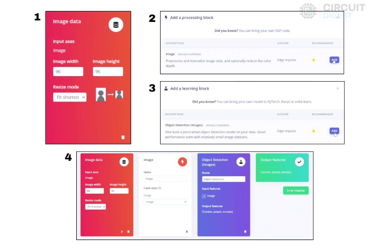
- As we are at the initial stage, there are not many options available. For the image data, we are going to leave the default image height and width as 96 x 96. You can change this according to your needs. If you increase the dimensions, the accuracy will improve but so will the training time. So, choose wisely.
- Next, in resize mode, the default will be "Fit shortest" You can select this based on the bounding box that you have drawn and the resolution of the photo you set.
- Next, add the processing block as "Image" as we are going to do image processing in object detection. Then, in the learning block, add "Object Detection."
- In output features, you can see the array of features that it is going to process.
- Now, click “Save Impulse”
Next, let's see about generating features.
Step 5: Generating Features
Here, we are in the processing block, which means we are processing the raw features to enhance feature importance. Let’s see how it works.
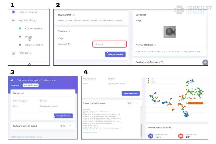
As usual, the whole procedure is added above for pictorial reference.
- First, select the "Image" option in the left menu column. Now you can see the Raw Feature, Parameter, and DSP Result.
- In the parameters, select "Grayscale" to reduce the load on the overall system. At this time, you can see the changes in the DSP result.
- Now click “Save parameters,” and then you can see the option to “Generate features.” Click that.
- Once the feature generation starts, after a few seconds, you can see the detailed report generated and displayed in the feature explorer. Above, in the fourth step, you can see a chart representation of the features generated by my dataset. Mostly, in this chart, every color represents an individual label. If the colors mix with each other, it means the features of those labels are quite similar. In that case, we need to do some tinkering with the dataset that we provided or change dimensions to make the job. Only when each color is grouped separately does it mean that this ML model would have greater accuracy.
Next, let's go to the main part of training the model.
Step 6: Training the Model
Here, we are going to configure the neural network and start the training process.
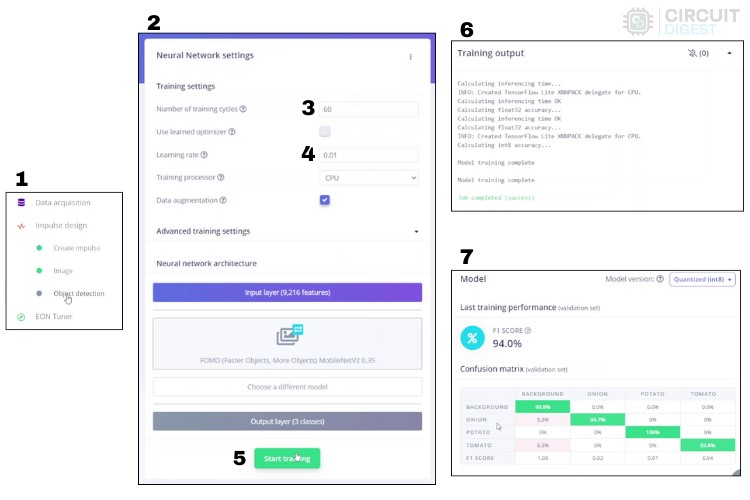
The above image shows the step-by-step process for configuring the neural network and training.
Here, let's look at the important parameters that are modified:
Number of Training Cycles: An epoch, or training cycle, is when the training algorithm goes through all the training data once and updates the model's parameters using back-propagation. Increasing epochs can improve model accuracy but may lead to overfitting while decreasing epochs can prevent overfitting but might result in underfitting.
Learning Rate: The learning rate controls how much the model's parameters change with each training step. It determines how fast the neural network learns. If the model learns too quickly and overfits, you can lower the learning rate.
Setting the right values is quite challenging. After some trial and error, you can find an optimum value.
After setting the right values, press “Start training.” It takes some time to complete, considering the number of training cycles and the learning rate, so sit back and relax.
Once training is completed, you can view the training performance in which the F1 score explains the accuracy of the system. The bigger the number, the greater the accuracy.
Finally, let's move to the deployment of the model.
Step 7: Deployment of the Model
First, click the "Deployment" option available in the left-side menu column, and you will see the deployment page. Talking about deployment, there are multiple options. You can even use your browser to check the model in real-time. So, check out the page for more information.
Now, we are going to do four things:
- Go to the deployment page.
- Select "Arduino Library" as a deployment option.
- Change the target to "Espressif ESP-EYE (ESP32 240MHz)."
- Click on "Build."
This will start the process of building a dedicated library that you will be installing in your Arduino IDE.
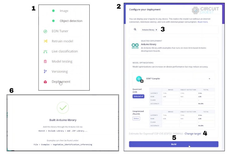
The above image shows the process of building the Arduino library, which consists of the trained model. This downloaded file is the esp32 cam object detection code. You can directly install this in the Arduino IDE. Let's see the steps in detail.
Uploading Edge Impulse Code to ESP32-CAM
Now, let's install the Arduino library downloaded from Edge Impulse in the Arduino IDE by following the steps below:
- Extract the zip folder that is downloaded after the completion of the build. In my case, the zip folder is named “ei-vegetables-identification-arduino-1.0.1.zip.”
- Inside the extracted folder, you can find a folder named after your project title followed by the word “inferencing.” In my case, it is “Vegetables_Identification_inferencing.”
- Copy this folder and paste it into Documents->Arduino->libraries.
- Restart the Arduino IDE, and you are ready to upload the code to ESP32-CAM.
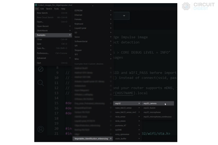
Once you have restarted the Arduino IDE, open the example program from the installed library. For reference, refer to the image below.
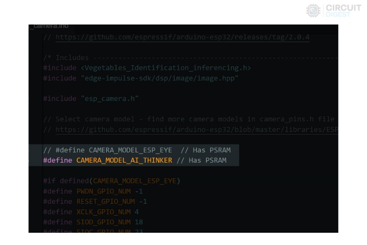
In the program, there is only one modification that we need to do, which is commenting out the line ‘#define CAMERA_MODEL_ESP_EYE’ and uncommenting the line ‘#define CAMERA_MODEL_AI_THINKER’ at the beginning of the code. For your reference, the screenshot is added below.
The next step is obviously uploading the code to ESP32-CAM. Upload the code, and the following step will be the working demonstration.
Working Demonstration of ESP32 CAM Object Recognition Project
Place the ESP32-CAM in the right position and direction, ensuring the camera can view the object clearly. I am going to use a small mobile phone tripod stand for mounting the ESP32-CAM at the perfect height and distance.
Above, you can see the hardware being connected to a tripod. Next, after the example program is uploaded, open the serial monitor in the Arduino IDE. You should see that the device has already started printing a set of statements, which show the detected object.
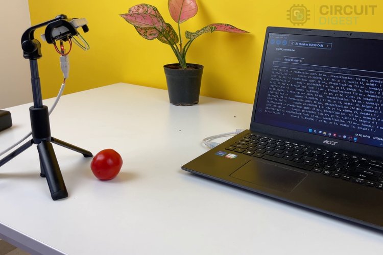
Above, you can see the image demonstrating the uploaded code in real-time. Yes, it actually detects the tomato without any problem. And hence, we have completed our project. But as I mentioned, I am going to use an OLED display to make this project more effective. So I have modified the esp32 cam object detection code to include an OLED display, you can find the complete code at the bottom of this page. You can also check out our esp32 cam object detection github page to download the code.
After making all the necessary changes, upload the modified code, and you will see the best results.
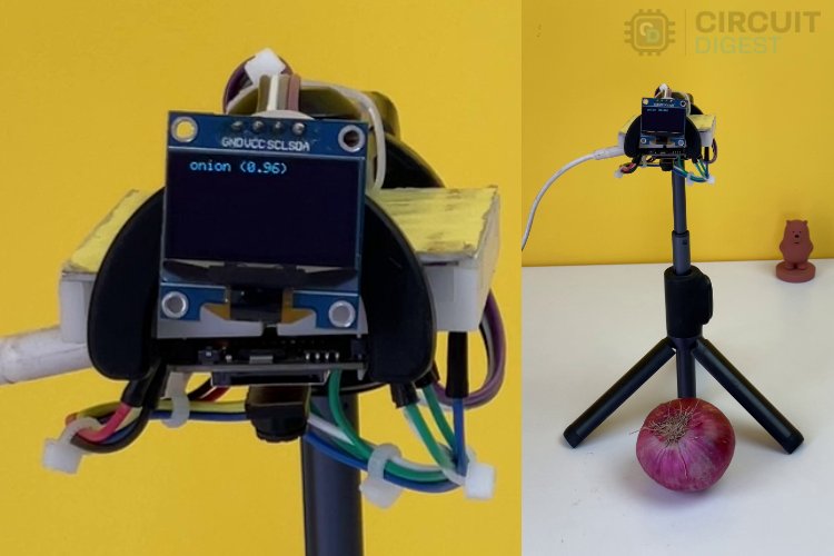
Above, you can see the image demonstrating the modified code, which shows the output on the OLED display.
Conclusion
We have successfully completed a machine learning project using Edge Impulse. However, the capabilities of Edge Impulse extend far beyond this project. There are countless possibilities for applying this powerful platform. We encourage you to explore more and discover the full potential of Edge Impulse for your future projects. Happy learning!
Here’s the GitHub repo where you can find the complete code and the circuit diagrams used for the final demonstration in this article.

/*
*ESP32 cam object detection code
* by circuirdigest on 27-June-2024
*/
#include <xxxx_inferencing.h> // modify with your project title, Replace the xxxx
#include "edge-impulse-sdk/dsp/image/image.hpp"
#include "esp_camera.h"
// Select camera model - find more camera models in camera_pins.h file here
// https://github.com/espressif/arduino-esp32/blob/master/libraries/ESP32/…
// #define CAMERA_MODEL_ESP_EYE // Has PSRAM
#define CAMERA_MODEL_AI_THINKER // Has PSRAM
#if defined(CAMERA_MODEL_ESP_EYE)
#define PWDN_GPIO_NUM -1
#define RESET_GPIO_NUM -1
#define XCLK_GPIO_NUM 4
#define SIOD_GPIO_NUM 18
#define SIOC_GPIO_NUM 23
#define Y9_GPIO_NUM 36
#define Y8_GPIO_NUM 37
#define Y7_GPIO_NUM 38
#define Y6_GPIO_NUM 39
#define Y5_GPIO_NUM 35
#define Y4_GPIO_NUM 14
#define Y3_GPIO_NUM 13
#define Y2_GPIO_NUM 34
#define VSYNC_GPIO_NUM 5
#define HREF_GPIO_NUM 27
#define PCLK_GPIO_NUM 25
#elif defined(CAMERA_MODEL_AI_THINKER)
#define PWDN_GPIO_NUM 32
#define RESET_GPIO_NUM -1
#define XCLK_GPIO_NUM 0
#define SIOD_GPIO_NUM 26
#define SIOC_GPIO_NUM 27
#define Y9_GPIO_NUM 35
#define Y8_GPIO_NUM 34
#define Y7_GPIO_NUM 39
#define Y6_GPIO_NUM 36
#define Y5_GPIO_NUM 21
#define Y4_GPIO_NUM 19
#define Y3_GPIO_NUM 18
#define Y2_GPIO_NUM 5
#define VSYNC_GPIO_NUM 25
#define HREF_GPIO_NUM 23
#define PCLK_GPIO_NUM 22
#else
#error "Camera model not selected"
#endif
/* Constant defines -------------------------------------------------------- */
#define EI_CAMERA_RAW_FRAME_BUFFER_COLS 320
#define EI_CAMERA_RAW_FRAME_BUFFER_ROWS 240
#define EI_CAMERA_FRAME_BYTE_SIZE 3
#include <Wire.h>
#include <Adafruit_GFX.h>
#include <Adafruit_SSD1306.h>
// ESP32-CAM doesn't have dedicated i2c pins, so we define our own. Let's choose 15 and 14
#define I2C_SDA 15
#define I2C_SCL 14
TwoWire I2Cbus = TwoWire(0);
// Display defines
#define SCREEN_WIDTH 128
#define SCREEN_HEIGHT 64
#define OLED_RESET -1
#define SCREEN_ADDRESS 0x3C
Adafruit_SSD1306 display(SCREEN_WIDTH, SCREEN_HEIGHT, &I2Cbus, OLED_RESET);
/* Private variables ------------------------------------------------------- */
static bool debug_nn = false; // Set this to true to see e.g. features generated from the raw signal
static bool is_initialised = false;
uint8_t *snapshot_buf; //points to the output of the capture
static camera_config_t camera_config = {
.pin_pwdn = PWDN_GPIO_NUM,
.pin_reset = RESET_GPIO_NUM,
.pin_xclk = XCLK_GPIO_NUM,
.pin_sscb_sda = SIOD_GPIO_NUM,
.pin_sscb_scl = SIOC_GPIO_NUM,
.pin_d7 = Y9_GPIO_NUM,
.pin_d6 = Y8_GPIO_NUM,
.pin_d5 = Y7_GPIO_NUM,
.pin_d4 = Y6_GPIO_NUM,
.pin_d3 = Y5_GPIO_NUM,
.pin_d2 = Y4_GPIO_NUM,
.pin_d1 = Y3_GPIO_NUM,
.pin_d0 = Y2_GPIO_NUM,
.pin_vsync = VSYNC_GPIO_NUM,
.pin_href = HREF_GPIO_NUM,
.pin_pclk = PCLK_GPIO_NUM,
//XCLK 20MHz or 10MHz for OV2640 double FPS (Experimental)
.xclk_freq_hz = 20000000,
.ledc_timer = LEDC_TIMER_0,
.ledc_channel = LEDC_CHANNEL_0,
.pixel_format = PIXFORMAT_JPEG, //YUV422,GRAYSCALE,RGB565,JPEG
.frame_size = FRAMESIZE_QVGA, //QQVGA-UXGA Do not use sizes above QVGA when not JPEG
.jpeg_quality = 12, //0-63 lower number means higher quality
.fb_count = 1, //if more than one, i2s runs in continuous mode. Use only with JPEG
.fb_location = CAMERA_FB_IN_PSRAM,
.grab_mode = CAMERA_GRAB_WHEN_EMPTY,
};
/* Function definitions ------------------------------------------------------- */
bool ei_camera_init(void);
void ei_camera_deinit(void);
bool ei_camera_capture(uint32_t img_width, uint32_t img_height, uint8_t *out_buf);
/**
* @brief Arduino setup function
*/
void setup() {
// put your setup code here, to run once:
Serial.begin(115200);
// Initialize I2C with our defined pins
I2Cbus.begin(I2C_SDA, I2C_SCL, 100000);
// SSD1306_SWITCHCAPVCC = generate display voltage from 3.3V internally
if (!display.begin(SSD1306_SWITCHCAPVCC, SCREEN_ADDRESS)) {
Serial.printf("SSD1306 OLED display failed to initalize.\nCheck that display SDA is connected to pin %d and SCL connected to pin %d\n", I2C_SDA, I2C_SCL);
while (true)
;
}
//comment out the below line to start inference immediately after upload
while (!Serial)
;
Serial.println("Edge Impulse Inferencing Demo");
if (ei_camera_init() == false) {
ei_printf("Failed to initialize Camera!\r\n");
} else {
ei_printf("Camera initialized\r\n");
}
ei_printf("\nStarting continious inference in 2 seconds...\n");
display.clearDisplay();
display.setCursor(0, 0);
display.setTextSize(1);
display.setTextColor(SSD1306_WHITE);
display.print("Starting continious\n inference in\n 2 seconds...");
display.display();
ei_sleep(2000);
display.clearDisplay();
}
/**
* @brief Get data and run inferencing
*
* @param[in] debug Get debug info if true
*/
void loop() {
display.clearDisplay();
// instead of wait_ms, we'll wait on the signal, this allows threads to cancel us...
if (ei_sleep(5) != EI_IMPULSE_OK) {
return;
}
snapshot_buf = (uint8_t *)malloc(EI_CAMERA_RAW_FRAME_BUFFER_COLS * EI_CAMERA_RAW_FRAME_BUFFER_ROWS * EI_CAMERA_FRAME_BYTE_SIZE);
// check if allocation was successful
if (snapshot_buf == nullptr) {
ei_printf("ERR: Failed to allocate snapshot buffer!\n");
return;
}
ei::signal_t signal;
signal.total_length = EI_CLASSIFIER_INPUT_WIDTH * EI_CLASSIFIER_INPUT_HEIGHT;
signal.get_data = &ei_camera_get_data;
if (ei_camera_capture((size_t)EI_CLASSIFIER_INPUT_WIDTH, (size_t)EI_CLASSIFIER_INPUT_HEIGHT, snapshot_buf) == false) {
ei_printf("Failed to capture image\r\n");
free(snapshot_buf);
return;
}
// Run the classifier
ei_impulse_result_t result = { 0 };
EI_IMPULSE_ERROR err = run_classifier(&signal, &result, debug_nn);
if (err != EI_IMPULSE_OK) {
ei_printf("ERR: Failed to run classifier (%d)\n", err);
return;
}
// print the predictions
ei_printf("Predictions (DSP: %d ms., Classification: %d ms., Anomaly: %d ms.): \n",
result.timing.dsp, result.timing.classification, result.timing.anomaly);
#if EI_CLASSIFIER_OBJECT_DETECTION == 1
bool bb_found = result.bounding_boxes[0].value > 0;
for (size_t ix = 0; ix < result.bounding_boxes_count; ix++) {
auto bb = result.bounding_boxes[ix];
if (bb.value == 0) {
continue;
}
ei_printf(" %s (%f) [ x: %u, y: %u, width: %u, height: %u ]\n", bb.label, bb.value, bb.x, bb.y, bb.width, bb.height);
display.setCursor(0, 20 * ix);
display.setTextSize(2);
display.setTextColor(SSD1306_WHITE);
display.print(bb.label);
display.print("-");
display.print(int((bb.value)*100));
display.print("%");
display.display();
}
if (!bb_found) {
ei_printf(" No objects found\n");
display.setCursor(0, 16);
display.setTextSize(2);
display.setTextColor(SSD1306_WHITE);
display.print("No objects found");
display.display();
}
#else
for (size_t ix = 0; ix < EI_CLASSIFIER_LABEL_COUNT; ix++) {
ei_printf(" %s: %.5f\n", result.classification[ix].label,
result.classification[ix].value);
}
#endif
#if EI_CLASSIFIER_HAS_ANOMALY == 1
ei_printf(" anomaly score: %.3f\n", result.anomaly);
#endif
free(snapshot_buf);
}
/**
* @brief Setup image sensor & start streaming
*
* @retval false if initialisation failed
*/
bool ei_camera_init(void) {
if (is_initialised) return true;
#if defined(CAMERA_MODEL_ESP_EYE)
pinMode(13, INPUT_PULLUP);
pinMode(14, INPUT_PULLUP);
#endif
//initialize the camera
esp_err_t err = esp_camera_init(&camera_config);
if (err != ESP_OK) {
Serial.printf("Camera init failed with error 0x%x\n", err);
return false;
}
sensor_t *s = esp_camera_sensor_get();
// initial sensors are flipped vertically and colors are a bit saturated
if (s->id.PID == OV3660_PID) {
s->set_vflip(s, 1); // flip it back
s->set_brightness(s, 1); // up the brightness just a bit
s->set_saturation(s, 0); // lower the saturation
}
#if defined(CAMERA_MODEL_M5STACK_WIDE)
s->set_vflip(s, 1);
s->set_hmirror(s, 1);
#elif defined(CAMERA_MODEL_ESP_EYE)
s->set_vflip(s, 1);
s->set_hmirror(s, 1);
s->set_awb_gain(s, 1);
#endif
is_initialised = true;
return true;
}
/**
* @brief Stop streaming of sensor data
*/
void ei_camera_deinit(void) {
//deinitialize the camera
esp_err_t err = esp_camera_deinit();
if (err != ESP_OK) {
ei_printf("Camera deinit failed\n");
return;
}
is_initialised = false;
return;
}
/**
* @brief Capture, rescale and crop image
*
* @param[in] img_width width of output image
* @param[in] img_height height of output image
* @param[in] out_buf pointer to store output image, NULL may be used
* if ei_camera_frame_buffer is to be used for capture and resize/cropping.
*
* @retval false if not initialised, image captured, rescaled or cropped failed
*
*/
bool ei_camera_capture(uint32_t img_width, uint32_t img_height, uint8_t *out_buf) {
bool do_resize = false;
if (!is_initialised) {
ei_printf("ERR: Camera is not initialized\r\n");
return false;
}
camera_fb_t *fb = esp_camera_fb_get();
if (!fb) {
ei_printf("Camera capture failed\n");
return false;
}
bool converted = fmt2rgb888(fb->buf, fb->len, PIXFORMAT_JPEG, snapshot_buf);
esp_camera_fb_return(fb);
if (!converted) {
ei_printf("Conversion failed\n");
return false;
}
if ((img_width != EI_CAMERA_RAW_FRAME_BUFFER_COLS)
|| (img_height != EI_CAMERA_RAW_FRAME_BUFFER_ROWS)) {
do_resize = true;
}
if (do_resize) {
ei::image::processing::crop_and_interpolate_rgb888(
out_buf,
EI_CAMERA_RAW_FRAME_BUFFER_COLS,
EI_CAMERA_RAW_FRAME_BUFFER_ROWS,
out_buf,
img_width,
img_height);
}
return true;
}
static int ei_camera_get_data(size_t offset, size_t length, float *out_ptr) {
// we already have a RGB888 buffer, so recalculate offset into pixel index
size_t pixel_ix = offset * 3;
size_t pixels_left = length;
size_t out_ptr_ix = 0;
while (pixels_left != 0) {
// Swap BGR to RGB here
// due to https://github.com/espressif/esp32-camera/issues/379
out_ptr[out_ptr_ix] = (snapshot_buf[pixel_ix + 2] << 16) + (snapshot_buf[pixel_ix + 1] << 8) + snapshot_buf[pixel_ix];
// go to the next pixel
out_ptr_ix++;
pixel_ix += 3;
pixels_left--;
}
// and done!
return 0;
}
#if !defined(EI_CLASSIFIER_SENSOR) || EI_CLASSIFIER_SENSOR != EI_CLASSIFIER_SENSOR_CAMERA
#error "Invalid model for current sensor"
#endif
Comments
Edit the file ei_classifier…
Edit the file ei_classifier_config.h in exported Arduino library folder: /scr/edge-impulse-sdk/classifier/: and set #define EI_CLASSIFIER_TFLITE_ENABLE_ESP_NN from 1 to 0

hi , i am having a issue with the uploading the code it says
