Water tank overflow is a common problem that results in water wastage, and it's surprising to note that it's not even considered a concern in many households. Though there are many solutions for it like ball valves that automatically cut the flow of water when a certain level is reached but as an electronic engineer, I prefer a solution that includes sensors and automation. So, in this tutorial, we are going to interface a water level sensor with Arduino to measure the water level and in the process, we will let you know the details about this sensor and its working. So, without further ado, let's get right into it.
Water Level Sensor Pinout
The working principle of the water level sensor module is very similar to that of a Rain Sensor.
The water level sensor has three pins, runs on 5V power, and gives out the data in analog format. The pinout of the water level sensor is given below:
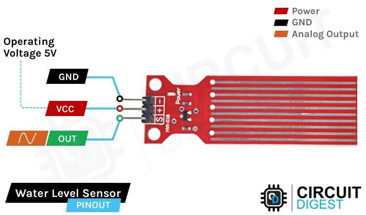
VCC is the power supply pin of the Rain Detection Sensor that can be connected to 5V of the supply.
GND is the ground pin of the board, and it should be connected to the ground pin of the Arduino.
OUT is the Analog output pin of the board that will give us an analog signal in between VCC and ground.
Water Level Sensor Specifications
You can find the specifications of the Water Level Sensor below,
- Operating Voltage Range - 3 to 5 V
- Current Consumption - 3 to 41 mA
- Output Voltage Range - 0 to 3.85 V
- Sensor Output Type - Typically Analog, but possible to interface with Digital Pins
- Water Detection Area - 40mm Height x 16mm Width
- Operating Humidity - 10% to 90%
- Working Temperature - -30 to 50 °C
It is suggested not to operate the sensor with more than 5V as higher voltage increases current consumption, which also proportionally increases the act of electrolysis in the liquid medium and may result in changing some characteristics of that liquid. One thing to note is that the output voltage will not be constant for a particular level of water over time due to the process of electrolysis, but as per observation, it is quite stable in water that is in motion.
How does a Water Level Sensor Work?
The working of the water level sensor is pretty simple and easy to understand. The PCB is made out of long conductive plates. When the water reaches a certain level, the resistivity between the two plates changes, which is responsible for the variable output voltage.
The above GIFs show the working of the water level sensor in action. As you can see, when the drop of water falls inside the glass, the water level rises, and the voltage on the output pin also rises. This change in voltage output happens because of the sensor’s water detection portion on the PCB, which is made out of 10 conducting plates. Five of these plates are power tracks, and the other five are sensor tracks, causing the resistance between them to change.
If you plot the change in water level and output voltage as a graph, you will notice that the graph looks parabolic and exponential.
Water Level Sensor – Parts
This sensor is very simple, so it can be made with very few parts. This sensor produces the water level and outputs the data in an analog format. The parts marking of the sensor is shown below.
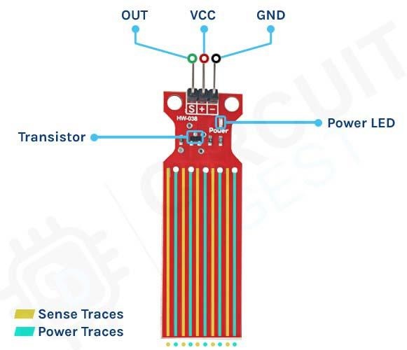
The sensor module has three pins, two of those are power pins and needs to be connected to the 5V and ground pin of the Arduino. As you can see in the above picture, the module has a single power LED that turns on when power is applied to the board, other than that we also have a transistor and a bunch of resistors that in total makes the water level sensor module.
Circuit Diagram for Water Level Sensor Module
The Schematic Diagram of the Water Level Sensor is shown below and as you can see it's pretty simple to understand.

In the schematic, the collector of the transistor is connected to the supply voltage of 5V, and the emitter is connected to the ground with a 100 Ohms resistor. In the module, a set of 5 conducting plates are connected with the vcc in series with a 100 Ohms resistor and the other 5 sets are connected to the base of the NPN transistor. Now when the water touches these conducting palates, currents start flowing from the 5V supply to the base of the transistor, and the transistor turns on. The more submerged the sensor is, the more output voltage it will generate.
Arduino Water Level Sensor Circuit – Connection Diagram
Now that we completely understand how the water level sensor works, we can connect all the required wires to the Arduino UNO board, and in this section of the article, we will discuss just that!
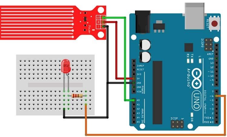
In the above figure, the connection diagram for the water level sensor with Arduino is shown. We have connected an LED to the PWM pin6 of the Arduino board and the analog output pin of the sensor is connected to the A0 pin. The ground pin is common in between the module and the LED, and the VCC is taken from the 5V pin of the Arduino. We will program the Arduino so that the brightness of the LED will change depending on the water level sensed by the sensor.
Arduino Code for Interfacing Water Level Sensor Module with Arduino
The Arduino water level sensor code is explained below. The code is very simple and easy to understand. We just have to read the analog data out of the sensor, and we can approximate the average water level with the ADC of the Arduino.
We initialize our code by declaring two macros, the first one is for the LED, where we will connect an LED and the second one is the sensorPin through which we are reading the data coming out of the sensor.
// Sensor pins pin D6 LED output, pin A0 analog Input
#define ledPin 6
#define sensorPin A0
Next, we have our setup() function. In the setup function, we initialize the serial with 9600 baud. We also set the ledPin as output, and make the pin LOW. This way the pin will not float and turn the LED on.
void setup() {
  Serial.begin(9600);
  pinMode(ledPin, OUTPUT);
  digitalWrite(ledPin, LOW);
}
Next, we have our loop function; in the loop function we read the sensor pin and stored it in a local variable named sensorValue. Then, we defined an if condition in which we check if the incoming value from the sensor is greater than 570, if so, we map the value with the help of the inbuilt map function of the Arduino and finally, we generate the PWM signal with the help of analogWrite function, the final serial.print function is there for debugging.
void loop() {
  int sensorValue = analogRead(sensorPin);
  if (sensorValue > 570)  {
    int outputValue = map(sensorValue, 570, 800, 0, 255);
    Serial.println(outputValue);
    analogWrite(ledPin, outputValue); // generate PWM signal
  }
}
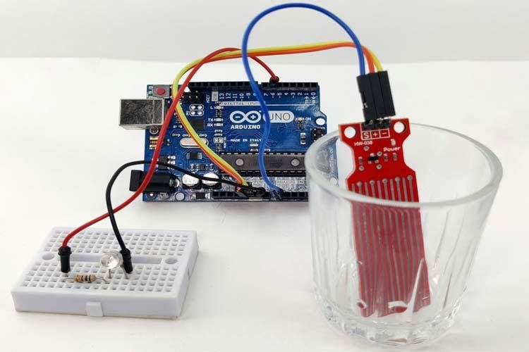
Working of the Arduino Water Level Sensor
The gif down below shows the Water Level Sensor working. At first, you can see that the LED on the breadboard is off but when we put some water on the glass, the brightness of the LED starts to increase and when the water in the glass is full the LED glows at full brightness.
One problem we have encountered while working with this sensor is that the bottom portion of this sensor is very sensitive, while the top portion is not that sensitive. If the water level crosses the bottom portion, the sensitivity almost goes to maximum, and it saturates.
Bonus Example:
Above we made a simple demo of the working of the Water Level Sensor using a LED as output. Now we will add 3 LEDs Showing 3 stages of the Water level as Low, Medium, and High respectively. First Lets discuss the Circuit Diagram.
Arduino Water Level Sensor with 3 LEDs as output – Circuit Diagram
Below you can see the circuit diagram of the Water Level Sensor Circuit along with three LEDs for showing the Demonstration.
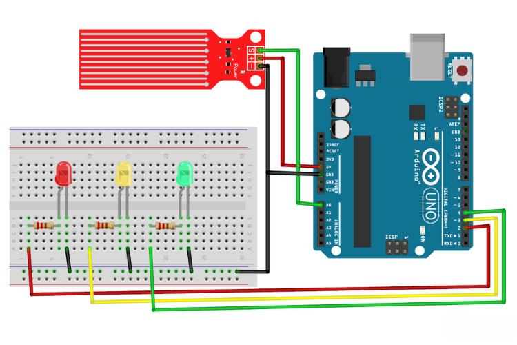
In this circuit, an extra two LEDs were connected, else are same as in the previous demonstration with a single LED. Following we can goto the code explanation for this demo.
Next, let's see the Coding Part.
Arduino Code for Water Level Sensor with 3 LED as output:
Here Most of the code is similar to above project. As we are going to deal with 3 LEDs we are adding three additional OUTPUT as in the below code.
#define lowOutput  2
#define mediumOutput  3
#define highOutput  4
Next Comes the Void Loop Section. Here the Analog DataFrom sensorPin is read and passed to the if else statements. The values 280, 564 & 640 are found by trial and error method.
void loop() {
  int sensorValue = analogRead(sensorPin);

  if (280 > sensorValue) {
    digitalWrite(lowOutput, HIGH);
    digitalWrite(highOutput, LOW);
    digitalWrite(mediumOutput, LOW);
  }  else if (564 > sensorValue) {
    digitalWrite(mediumOutput, HIGH);
    digitalWrite(highOutput, LOW);
    digitalWrite(lowOutput, LOW);
  } else if (640 > sensorValue) {
    digitalWrite(highOutput, HIGH);
    digitalWrite(mediumOutput, LOW);
    digitalWrite(lowOutput, LOW);
  } else {
    digitalWrite(highOutput, LOW);
    digitalWrite(mediumOutput, LOW);
    digitalWrite(lowOutput, LOW);
  }
  delay(100);
}
You can find your own by verifying the sensor with you. Its very simple by following the below steps.
- Open the file AnalogReadSerial which you can find in “File -> Examples -> 01.Basics -> AnalogReadSerial“.
- Connect the sensor with arduino and read the data output via serial Monitor.
- For 3 states of the water level, note the respective output adc values. And you can use that in the present Code.
While taking the readings you might notice that the output won't be linear, actually it will be a exponential curve when you plotted in a map.
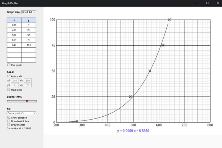
In the above graph, X represents the output value of the ADC and Y represents the respective level of the water. So, you can clearly see that it was an exponential curve. And if you wonder about the software I used, it is Graph Plotter which is available in the Microsoft store. You can use whatever software, and the result will be the same.
So, the, if else statements are self-explanatory. For the set value the Defined LED will light up, stating the water level.
Next, let's move to the working demonstration.
Working of the Arduino Water Level Sensor with 3 LEDs as Output
Now let us move to the real-world working demonstration of 3 LED Output Water Level Indication Project. Here instead of a single LED, 3 LEDs were deployed to perfectly indicate the level of the Water in the Container.
Pros and Cons of using Water Level Sensor:
You can find more about this sensor once you experiment by yourself. The pros and cons below are based on our observations while doing multiple experiments with this water level sensor.
Pros:
This sensor is very simple to integrate with any microcontroller to detect the presence of liquid. It can interface with both analog and digital input pins. It is inexpensive compared to other water level sensors, making it ideal for budget projects.
Cons:
There is a problem with the accuracy of finding the water level due to the phenomenon of electrolysis, so it is most suited for only detecting the presence of liquid. Since this sensor uses PCB traces for detecting the water level, there is a possibility of water sticking to the surface of the PCB, which may lead to false sensing. Another issue is the nature of the output. As it is not linear, it requires a complex formula to find the range of the liquid level. This may not be an ideal solution for a product due to the electrolysis phenomenon, which may modify the nature of the liquid over time.
Projects in a Similar Realm
Following are some projects that are related in measuring water levels. If you are looking for more options, just explore them for more details:
Simple Water Level Indicator Alarm with Buzzer
If you are a beginner and want to build your own jelly bean water level sensor, this project is for you because here we have used some general purpose transit, some resistor, LEDs, and a buzzer to build a simple water level sensor.
Measure Water Level using JSN SR-40T Waterproof Ultrasonic Sensor
If you are thinking about building a simple yet effective water level sensor for day-to-day use, you can check out this project because in this project we have used an industrial-grade ultrasonic water level sensor to build a water level alarm which also shows the amount of water available in the tank.
Automatic Water Level Indicator and Controller using Arduino
If you are interested in building a simple water level sensor for home use this project can be for you, because in this project we have used an Arduino and some relays to build a simple water level display with an overflow alarm.
Commonly Asked Questions about Water Level Sensor Module
What are the types of water level sensors?
There are six basic types of commercially used water level indicators: Resistive, Capacitive, Ultrasonic, Frequency, Guided wave GWR, and Pressure transducers. Each of these commonly used indicators have benefits, and each has its drawbacks.
What are level sensors used for?
Water level sensors detect the level of liquids and other fluids and fluidized solids, including slurries, granular materials, and powders that exhibit an upper free surface.
Is it possible to make a water level indicator at home?
If you can accrue all the basic supplies like LEDs, a buzzer, and sensing wires. Then it is not hard to build a basic water level indicator.
Can ultrasonic sensors detect water levels?
With ultrasonic sensors, we can find the water depth calculation by finding the distance between the transceiver and the surface of the water. The sensor will transmit a short ultrasonic pulse, and we can measure the travel time of that pulse (the echo) to the liquid and back.
Supporting Files


Code for project with single LED as an OUTPUT:
//Arduino water level sensor code
// Sensor pins pin D6 LED output, pin A0 analog Input
#define ledPin 6
#define sensorPin A0
void setup() {
Serial.begin(9600);
pinMode(ledPin, OUTPUT);
digitalWrite(ledPin, LOW);
}
void loop()
{
unsigned int sensorValue = analogRead(sensorPin);
if (sensorValue < 540)
return;
uint8_t outputValue = map(sensorValue, 540, 800, 0, 255);
Serial.print(sensorValue);
Serial.print(" ");
Serial.println(outputValue);
analogWrite(ledPin, outputValue); // generate PWM signal
}
Code for project with Three LED as an OUTPUT:
//Arduino water level sensor code
// Sensor pins pin D6 LED output, pin A0 analog Input
#define sensorPin A0
#define lowOutput 2
#define mediumOutput 3
#define highOutput 4
void setup() {
Serial.begin(9600);
pinMode(lowOutput , OUTPUT);
pinMode(mediumOutput , OUTPUT);
pinMode(highOutput , OUTPUT);
digitalWrite(lowOutput, LOW);
digitalWrite(mediumOutput, LOW);
digitalWrite(highOutput, LOW);
}
void loop() {
int sensorValue = analogRead(sensorPin);
if (280 > sensorValue) {
digitalWrite(lowOutput, HIGH);
digitalWrite(highOutput, LOW);
digitalWrite(mediumOutput, LOW);
} else if (564 > sensorValue) {
digitalWrite(mediumOutput, HIGH);
digitalWrite(highOutput, LOW);
digitalWrite(lowOutput, LOW);
} else if (640 > sensorValue) {
digitalWrite(highOutput, HIGH);
digitalWrite(mediumOutput, LOW);
digitalWrite(lowOutput, LOW);
} else {
digitalWrite(highOutput, LOW);
digitalWrite(mediumOutput, LOW);
digitalWrite(lowOutput, LOW);
}
delay(100);
}