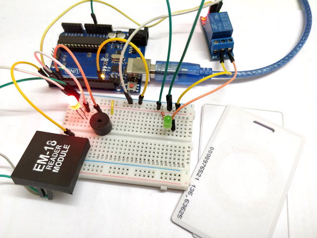
You have seen RFID Door Lock Mechanism in some Hotels and other places, where you don’t need a key to unlock the room. You are given a card and you just need to put it in front of a RFID Reader box, and the lock gets unlocked with a Beep and a Blink of LED. This RFID Door Lock can be made easily at your home and you can install it in any door. These Door lock is just electrically operating door lock which gets open when you apply some voltage (typically 12v) to it.
Here in this project we are using Arduino and relay to trigger the Electric Door Lock and RFID to authenticate, so your RFID tag will act as a key. If you place wrong RFID card near RFID reader a buzzer will beep to alert about wrong card. If you are new to RFID first read its working an interfacing with Arduino.
Material Required:
- Arduino UNO
- EM-18 Reader Module with Tags
- Relay 5v
- LED
- Buzzer
- Connecting wire
- Resistors
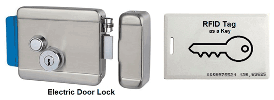
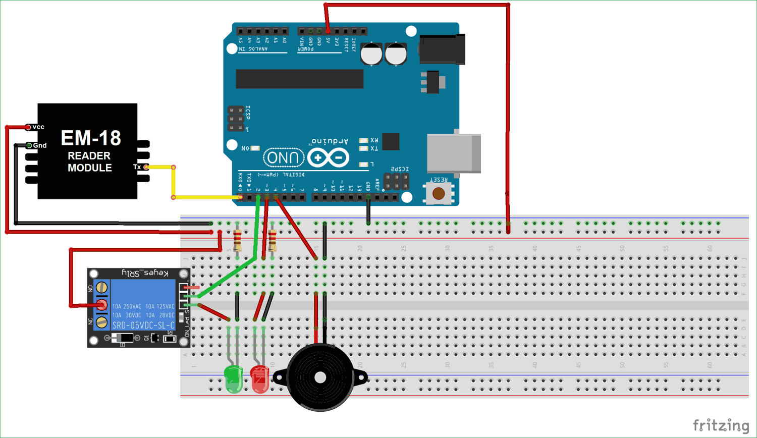
Arduino RFID Door Lock Circuit Diagram
EM-18 RFID Reader:
RFID stands for Radio Frequency Identification. Each RFID card has a unique ID embedded in it and a RFID reader is used to read the RFID card no. EM-18 RFID reader operates at 125 KHz and it comes with an on-chip antenna and it can be powered with 5V power supply. It provides serial output along with weigand output. The range is around 8-12cm. serial communication parameters are 9600bps, 8 data bits, 1 stop bit. This wireless RF Identification is used in many systems like
Check all the RFID Projects here.
The output provided by EM-18 RFID reader is in 12 digit ASCII format. Out of 12 digits first 10 digits are card number and the last two digits are the XOR result of the card number. Last two digits are used for error checking.
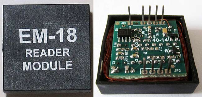
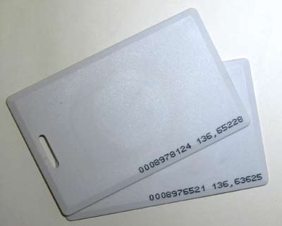
For example, card number is 0200107D0D62 read from the reader then the card number on the card will be as below.
02 – Preamble
00107D0D = 1080589 in decimal.
62 is XOR value for (02 XOR 00 XOR 10 XOR 7D XOR 0D).
Hence number on the card is 0001080589
Code and Explanation:
The complete RFID Door Lock Arduino Code is given at the end of this project.
In the below code, the RFID tag number are stored in the “char tag”. "180088F889E1" is my RFID tag number stored in the microchip of the Transponder. The length of the tag number is 12 we have defined the array like “char input [12]”, 12 defines the no. of character or size of array.
char tag[] ="180088F889E1";
char input[12];
int count = 0;
boolean flag = 0;
For find the tag no. of your Arduino you can refer this article.
Now, in below code, we setup the pins of the Arduino UNO board for the operation and the serial.begin() is used for the serial data transmission. Here the pin 2 is used for the relay operation, pin 3 is for the standby red LED and pin 4 is for the buzzer.
void setup()
{
  pinMode(2,OUTPUT);
  pinMode(3, OUTPUT);
  pinMode(4, OUTPUT);
  Serial.begin(9600);
}
The conditional body of the code is void loop() , for the standby red LED the pin 3 remains HIGH until any task performed.
We will check if there is any serial data available using the if condition. Means we will check if there is any RFID tag is getting scanned. If any serial data (RFID Tag no.) is coming we will save it in input[] array which we defined for saving RFID tag number.
  void loop(
{
  digitalWrite(3,1);
  if(Serial.available())
  {
    count = 0;
  while(Serial.available() && count < 12)
    {
      input[count] = Serial.read();
      count++;
      delay(5);
    }
Now we will compare the scanned RFID card no. with the number which we have defined in char tag[] array. If both the umber matches then we set the flag variable to 1 and if the wrong card is scanned or both the numbers don’t match then we set the flag variable to 0.
    if(count == 12)
    {
      count =0;
      flag = 1;
      while(count<12 && flag !=0)
      {
        if(tag[count]==input[count])
        flag = 1;
        else
        flag= 0;
}
If you place right RFID tag, the flag gets equal to 1, in this case the pin 2 goes HIGH (through which a relay operated) and the pin 3 goes low at this moment, after delay of 5 sec both pins will return to its initial condition. Relay will be further connected to Electric Door Lock, so with the relay turned on, the Door Lock will be opened, and after 5 seconds it will again get locked.
    if(flag == 1)
    {
      digitalWrite(2,HIGH);
       digitalWrite(3,LOW);
      delay(5000);
      digitalWrite(2,LOW);
    }
If you place the wrong RFID card, the flag will be zero and the buzzer start beeping alerting that the RFID card is wrong.
     if(flag == 0)
      {
       for(int k =0; k<= 10; k++)
      {
        digitalWrite(4,HIGH);
        delay(300);
        digitalWrite(4,LOW);
        delay(300);
        }
        }
Working of Arduino Based RFID Door Lock
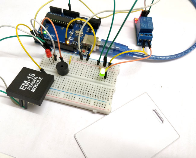
The RFID system consists of two components: an RFID tag and a Reader. The RFID tag consist of integrated circuit and an antenna, integrated circuit is for the storage of the data, and an antenna is for transmitting the data to the RFID Reader module. Whenever the RFID tag comes in the range of RFID reader, RF signal power the tag and then tag starts transmitting data serially. Data is further received by the RFID reader and the reader sends it to the Arduino board. And, after that as per the code in micro-controller different task performs.
In our circuit, we have already saved the value of RFID tag in the code. So, whenever that particular tag comes in range, the relay gets activated. Here we have connected a LED with Relay to demonstrate, but this LED can be replaced by an Electric Door Lock, so that whenever the Relay gets activated the lock will be opened.
If we scan any other RFID card, the buzzer will start beeping as it’s the wrong RFID tag. Hence, for the door lock system we have used this concept that the door will only get opened by using the right RFID tag. The relay will itself get deactivated after 5 seconds, the door will be closed after 5 seconds, and you can change this delay in the code.
Complete code and Demonstration Video is given below.
char tag[] ="180088F889E1";
char input[12];
int count = 0;
boolean flag = 0;
void setup()
{
pinMode(2,OUTPUT);
pinMode(3, OUTPUT);
pinMode(4, OUTPUT);
Serial.begin(9600);
}
void loop()
{
digitalWrite(3,1);
if(Serial.available())
{
count = 0;
while(Serial.available() && count < 12)
{
input[count] = Serial.read();
count++;
delay(5);
}
if(count == 12)
{
count =0;
flag = 1;
while(count<12 && flag !=0)
{
if(tag[count]==input[count])
flag = 1;
else
flag= 0;
}
if(flag == 1)
{
digitalWrite(2,HIGH);
digitalWrite(3,LOW);
delay(5000);
digitalWrite(2,LOW);
}
if(flag == 0)
{
for(int k =0; k<= 10; k++)
{
digitalWrite(4,HIGH);
}
}
}
}
}
Comments
Em-18 reader
can I use another RFID cos I can't find EM-18 reader module
Yes you can use rc522. I just
Yes you can use rc522. I just made one last night but I used a different library and code
Both the resistors are used
Both the resistors are used only for limiting the current for the two LED. You can use a value of 560ohm or 1K it will work fine
Sir,Please provide the whole
Sir,Please provide the whole setup connectivity guide for RFID Door Lock based System
Rfid door lock
Please provide me the proper code and circuit ..I'm not getting output on this



Dear,
Can you ask someone to help me build digital scale with gsm support for beekeeping.
Thank you